
Data Sheet Chapter 5


500-Watt VHF Transmitter Chapter 5, Detailed Alignment Procedures
425A, Rev. 0 5-17
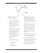
the LO frequency and minimum
out-of-band products. Adjust C13
and C17 for the best frequency
response for the LO frequency.
2. Adjust C3 and C6 to determine
the center frequency. Use C2 and
C7 to locate the upper and lower
channel-edge shaping. C4 is used
to determine the channel
bandwidth.
5.12.14 (A11-A3) High-Band VHF
Filter/Amplifier Board (1064252;
Appendix D)
The filter/amplifier board has been
factory swept and adjusted for a 6-MHz
bandwidth.
Note: This board should not be tuned
without the proper equipment.
The filtered output connects to J1 of the
board and is amplified by U1 to a
nominal +8 dBm visual and -2 dBm aural
level by adjusting R9. The output at J2 is
fed to J4 on the A11 enclosure and from
there to J15 on the rear of the tray.
To align the board, use a multiburst or
sweep video signal inserted into the
exciter tray.
Reconnect the cable from J6 to J1 on the
filter/amplifier board. Monitor J2, the RF
output of the board, and peak C17 for
the maximum signal level. Tune manual
gain adjust R9 for a +8 dBm peak visual
output.
This completes the detailed alignment
procedures for the 425A transmitter. If a
problem occurred during the alignment,
refer to the detailed alignment procedure
for that tray for more information.