
Data Sheet Chapter 5


500-Watt VHF Transmitter Chapter 5, Detailed Alignment Procedures
425A, Rev. 0 5-12
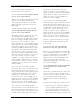
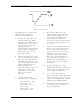
Figure 5-1. Waveform
7. The following test setup is for the
adjustment of the depth of
modulation and ICPM at IF:
A. Remove the cable that is on
J18 and connect the double-
sideband, 45.75-MHz visual IF
signal from J18 to a 10-dB
splitter/coupler. Connect the
coupled port of the
splitter/coupler to the RF input
of a television demodulator.
Connect the direct port to a
spectrum analyzer.
B. Connect the 75Ω video output
of the demodulator to the video
input of a waveform monitor.
For ICPM measurements, also
connect the quadrature output
of the demodulator to the
horizontal input of the
waveform monitor using a 250
-kHz, low-pass filter. (An
oscilloscope can be used in
place of a waveform
monitor).
C. Set the controls of the
demodulator to the following:
Detector mode – Cont
Sound trap – In
Zero carrier – On
Auto – Sync
Audio source – Split
De-emphasis – In
8. Move jumper W7 on J4 to the
Clamp Disable position. Readjust
pot R41, manual offset, for the
correct depth of modulation by
observing the demodulated
waveform on the waveform monitor
or on the spectrum analyzer set to
zero span.
9. Check the demodulated video for a
proper sync-to-video ratio (sync is
28.6% of the total white video
signal). If sync stretch is needed,
adjust R45, sync stretch cut-in,
until sync stretch occurs. Adjust
R48, sync stretch magnitude, for
the proper amount of stretch.
Readjust R41, manual offset, if
needed, for the correct depth of
modulation.
10. Move jumper W7 on J4 to the
Clamp Enable position. Readjust pot
R152, depth of modulation, for the
correct depth of modulation.
11. Set the waveform monitor to
display ICPM. Preset R53 fully CCW,
adjust C78 for the greatest effect at
white on the ICPM display, and then
adjust R53 for minimum ICPM.
12. Recheck the depth of modulation
and, if necessary, adjust R152,
depth of modulation.