
Data Sheet Chapter 5


500-Watt VHF Transmitter Chapter 5, Detailed Alignment Procedures
425A, Rev. 0 5-11
1. Adjust the filter with L2, C3, L4,
and C7 for a frequency response of
no greater than ±0.3 dB from 4.4
to 4.6 MHz.
2. Adjust C19 for an overall peak-to-
peak variation of less than ±0.3 dB
from 4.4 MHz to 4.6 MHz.
3. Recheck the frequency response; it
may have changed with the
adjustment of the envelope delay.
If necessary, retune the board.
5.12.5 (A7) IF Carrier Oven
Oscillator Board (1191-1404;
Appendix D)
To align this board:
1. While monitoring J3 with a
spectrum analyzer, observe the
45.75-MHz visual IF (typical +5
dBm).
2. Connect a frequency counter to J3
and adjust C17 for 45.750000 MHz.
3. Connect a frequency counter to J1
and check for 50 kHz, which is the
aural phase lock loop reference.
5.12.6 (A5) Sync Tip
Clamp/Modulator Board (1265-
1302; Appendix D)
To align this board:
1. Determine if jumper W4 on jack J3
is present. Jumper W4 terminates
the video input into 75Ω. Remove
jumper W4 if a video loop-through
is required on the rear chassis at
jacks J1 and J2.
2. Set the controls R20, the white clip,
R24, the sync clip, and R45, the
sync stretch cut-in, to their full
CCW position. Set R48, the sync
magnitude, fully CW and place the
jumper W7 on jack J4 to the
Clamp-Off, Disable, position.
3. Connect a 5-step staircase video
test signal to the input of the
transmitter.
4. Monitor TP2 with an oscilloscope.
Adjust R12, the video gain pot, for
1 Vpk-pk.
5. Change the video input test signal
to a multiburst test pattern. While
monitoring TP2, adjust C8 and R32
for a flat-frequency response.
Change the input video test signal
back to the 5-step staircase.
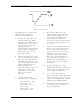
6. Monitor TP2 with an oscilloscope.
Adjust pot R41, manual offset, for a
blanking level of -0.8 VDC. The
waveform shown in Figure 5-1
should be observed. Move the
jumper W2 on J4 to the Clamp
Enable position. Adjust pot R152,
depth of modulation, for a blanking
level of -0.8 VDC.
Note: This waveform represents the
theoretical level for proper
modulation depth. Step 9 below
describes how to set the modulation
depth through the use of a television
demodulator or a zero-spanned
spectrum analyzer tuned to the
visual IF frequency.