
System Description Chapter 2

500-Watt VHF Low Band Transmitter Chapter 2, System Description
325A, Rev. 0 2-6
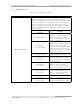
2.2.2 VHF Amplifier Tray
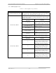
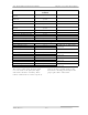
Table 2-6. VHF Amplifier Tray Switches
SWITCH FUNCTION
On/Off Circuit Breaker CB1
Switches 220 VAC through a 15-amp circuit breaker-type
protection device. The switch lights if AC is present. The AC
is applied to the switching power supply in the tray.
Selects the desired % Visual Forward Output Power, %
Visual Reflected Power reading, AGC Voltage, Power Supply
Voltage, or Current
With Switch S1 in
Position
Display
% Forward
Reads the % Forward Output
Power of the tray (100%= 500
watts peak of sync + aural)
% Refl (Reflected)
Reads the % Reflected Output
Power (<10%)
AGC Voltage
Reads the AGC level of the tray
(1 to 2 VDC)
Power Supply
Reads the voltage from the
switching power supply (+48
VDC)
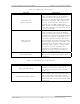
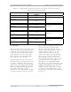
Switch S1, Meter
Current
Uses Switch S2 to indicate the
current of transistor devices
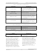
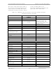
Selects the current of the transistor devices on the high
band amplifier boards. S1 must be in the Current position.
With Switch S2 in
Position
Display
I
1
Reads the current of (A3-A1)
the low band amplifier board
(idling current=2 amps and
operating current=5 amps)
I
2
Reads the current of (A3-A2)
the low band amplifier board
(idling current=2 amps and
operating current=5 amps)
I
3
Reads the current of (A3-A3)
the low band amplifier board
(idling current=2 amps and
operating current=5 amps)
Switch S2, Meter
I
D
Reads the current of (A2-A1)
the low band amplifier board
(idling current=3 amps and
operating current=3-4 amps)