
System Description Chapter 2

500-Watt VHF Low Band Transmitter Chapter 2, System Description
325A, Rev. 0 2-4
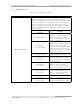
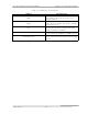
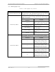
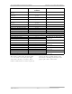
Table 2-3. VHF Exciter Tray Switches
SWITCH FUNCTION
Transmitter S1
Operate/Standby
The momentary switch S1 applies a ground
to K1, a latching relay on the transmitter
control board. K1 will switch either to
Operate or to Standby depending on which
direction S1 is pushed. When switched to
Operate, the low, Enable commands are
applied to the two VHF amplifier trays.
These Enables will turn on the VHF amplifier
trays. The opposite occurs when the switch
is turned to Standby.
Mode Select S2
Auto/Manual
The momentary switch S2 applies a ground
to K2, a latching relay on the transmitter
control board. K2 will switch the transmitter
to Automatic or Manual depending on which
direction S2 is pushed. In Automatic, the
video fault command from the ALC Board
will control the operation of the transmitter.
The transmitter will switch to Standby, after
a slight delay, if the input video is lost and
will switch back to Operate, quickly, when
the video is restored. In Manual, the
transmitter is controlled by the operator
using the front panel Operate/Standby
switch or by remote control.
Power Adjust (R1)
The 5 kΩ pot A20 sets the ALC level on the
ALC board to set the output power of the
transmitter.
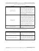
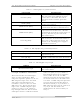
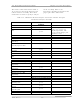
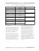
Table 2-4. VHF Exciter Tray Fault Indicators
INDICATOR DESCRIPTION
Video Loss (DS9 Red)
Indicates that the input video to the
transmitter has been lost. The fault is
generated on the ALC board in the VHF
exciter tray.
VSWR Cutback (DS7 Amber)
Indicates that the reflected power level of
the transmitter has increased above 20%;
this automatically cuts back the output
power level to 20%. The fault is generated
on the transmitter control board in the VHF
exciter tray.