
Installation Instructions Chapter 4


500-Watt VHF Low Band Transmitter Chapter 4, Installation and Setup Procedures
325A, Rev. 0 4-4
As with any equipment installation, it is
always good practice to consult the
manufacturer when questions arise.
Axcera can be contacted at (724) 873-
8100.
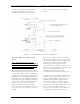
Figure 4-1. 1 kW Minimum Ventilation Configuration
4.2 Unpacking the Cabinets and
Trays
Note: Air conditioning and any
related heat exhaust ducts should be
in place before continuing with the
installation of the transmitter.
Thoroughly inspect the cabinets and all
other materials upon their arrival. Axcera
certifies that upon leaving our facility the
equipment was undamaged and in proper
working order. The shipping containers
should be inspected for obvious damage
that indicates rough handling. Check for
dents and scratches or broken switches,
meters, or connectors. Any claims
against in-transit damage should be
directed to the carrier. Inform Axcera as
to the extent of any damage as soon as
possible.
Remove the cabinet and the trays from
the crates and boxes. Remove the straps
that hold the cabinet to the shipping skid
and slide the cabinet from the skid.
Remove the plastic wrap and foam
protection from around the cabinet. Do
not remove any labeling or tags from any
cables or connectors; these are
identification markers that make
assembly of the transmitter much easier.
Remove the two L-brackets, mounted on
the front panel rails, which held the trays
in place during shipment. The trays are
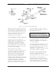
mounted in the cabinet using Chassis
Trak cabinet slides as shown in Figure
4-2. The tray slides are on the top and
the bottom of the VHF
amplifier trays and
on the sides of the VHF exciter tray.
Inspect the trays for any loose hardware
or connectors, tightening as needed.