
Data Sheet Chapter 5


500-Watt VHF Low Band Transmitter Chapter 5, Detailed Alignment Procedures
325A, Rev. 0 5-14
manual gain
DS3 (Red LED) Indicates a video loss fault
DS4 (Red LED) Indicates that a Mute command is present
DS5 (Green LED)
Indicates that the output from the
modulator is selected as the input to the
board
1. To align the ALC board, preset the
following controls on the tray:
A. ALC Board (1265-1305)
Connect jumper W1 on J4 to
disable, between pins 2 and 3 (to
disable linearity correctors).
Connect jumper W3 on J6 to
manual, between pins 2 and 3 (for
manual gain control).
Adjust R87, manual gain pot, to
mid-range.
B. IF Phase Corrector Board (1227-
1250)
Move W2 on J9 to phase
correction: enable. Move W3 on
J10 to amplitude correction:
disable.
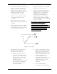
2. The combined IF output of the sync
tip clamp modulator board is cabled
to jack J32 of the ALC board.
Remove J32 from the board, and
look to see if DS1, Input Fault, is
illuminated. Reconnect J32 and
make sure that DS1 is
extinguished.
3. Jumper W3 on J6 should be in the
Manual position. Monitor jack J3
with a spectrum analyzer.
4. With a multiburst video signal
present, tune C4 for a flat-
frequency response of ±0.5 dB.
5. Before proceeding with the second
part of the ALC board alignment,
check to see that the IF phase
corrector board (1227-1250) is
functioning properly.
5.12.9 (A9) IF Phase Corrector Board
(1227-1250; Appendix D)
See Section 5.4 of this chapter for the
system alignment procedures for the IF
phase corrector board. The signal level
into the board should be approximately
the same as the output of the board.
The IF input jack of the IF phase
corrector board is fed from the J3 IF O/P
jack of (A8) the ALC board.
The IF output jack of the IF phase
corrector board is fed to the J7 IF I/P
jack of the ALC board (A8).
5.12.10 (A8) ALC Board, NTSC
(1265-1305; Appendix D) (Part 2 of
2)
To align this board:
1. Input a multiburst video test signal.
Connect a spectrum analyzer to
J11. Tune C63 for a flat-frequency
response of ±0.5 dB.
2. Move the Operate/Standby switch
on the front panel to the Operate
position.
3. Place jumper W3 on jack J6 in the
Manual mode and adjust R87 for
0.5 volts at TP4.
4. Place jumper W3 on J6 in the Auto
mode and adjust the front panel
power adjust control A20 fully CW.
If the (optional) remote power
raise/lower kit is present, then
adjust switch S1 on the board to
maximum voltage at TP4. Adjust
R74, the range adjust, for 1 volt at
TP4.