
Data Sheet Chapter 5


500-Watt VHF Low Band Transmitter Chapter 5, Detailed Alignment Procedures
325A, Rev. 0 5-13
5.12.7 (A4) Aural IF Synthesizer
Board, 4.5 MHz (1265-1303;
Appendix D)
1. To set up the test equipment for
this board:
A. Connect the 600Ω balanced
audio output from an audio
oscillator to the balanced audio
input terminals of the tray at
TB1-1 (+), TB1-2 (-), and TB1-
3 (ground) on the rear chassis.
B. Connect the combined IF
output at J21 (IF sample) on
the clamp modulator board to
the input of an IF splitter.
Connect one output of the
splitter to the video
demodulator and the other
output to the spectrum
analyzer.
C. At the front of the
demodulator, connect a short
cable from the RF-out jack to
the IF-in jack.
D. Connect a cable from the 600Ω
audio output jack of the
demodulator to the input of an
audio distortion analyzer.
2. Set the output frequency of the
audio oscillator to 400 Hz and the
output level to +10 dBm.
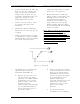
3. Center the aural carrier on the
spectrum analyzer with the
spectrum analyzer set to the
following:
Frequency/Division – 10 kHz
Resolution bandwidth – 3 kHz
Time/Division – 50 msec
Trigger – Free run
A. Adjust L5 for approximately
+3.5 VDC at TP2.
B. The green LED DS1 should be
illuminated, indicating a locked
condition. If not, retune L5 for
a locked condition.
4. Adjust R13, balanced audio gain, on
the aural IF synthesizer board for
±25-kHz deviation.
5. Check the distortion on the aural
distortion analyzer (THD=< 0.5%).
6. Disconnect the 600Ω balanced
audio input to the tray. Connect a
75Ω stereo audio input (400 Hz at 1
Vpk-pk) to composite audio input
jack J3 on the rear of the tray.
Follow the procedure in the stereo
generator instruction manual for
matching the level of the generator
to the exciter. Use R17 to adjust
the composite audio gain.
7. Check the distortion level on the
distortion analyzer (THD)=< 0.5%)
5.12.8 (A8) ALC Board (1265-1305;
Appendix D) (Part 1 of 2)
Table 5-2 describes the functions of each
LED on the ALC board (A8).
Table 5-2. ALC Board LEDs
LED FUNCTION
DS1 (Red LED)
Indicates that an abnormally low IF signal
level is present at IF input connector J1
DS2 (Red LED)
Indicates that the ALC circuit is unable to
maintain the level requested by the ALC
reference due to excessive attenuation in
the linearity or the IF phase corrector signal
path or because jumper W3 on J6 is in