
Data Sheet Chapter 5


500-Watt VHF Low Band Transmitter Chapter 5, Detailed Alignment Procedures
325A, Rev. 0 5-11
2. Set the controls R20, the white clip,
R24, the sync clip, and R45, the
sync stretch cut-in, to their full
CCW position. Set R48, the sync
magnitude, fully CW and place the
jumper W7 on jack J4 to the
Clamp-Off, Disable, position.
3. Connect a 5-step staircase video
test signal to the input of the
transmitter.
4. Monitor TP2 with an oscilloscope.
Adjust R12, the video gain pot, for
1 Vpk-pk.
5. Change the video input test signal
to a multiburst test pattern. While
monitoring TP2, adjust C8 and R32
for a flat-frequency response.
Change the input video test signal
back to the 5-step staircase.
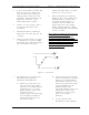
6. Monitor TP2 with an oscilloscope.
Adjust pot R41, manual offset, for a
blanking level of -0.8 VDC. The
waveform shown in Figure 5-1
should be observed. Move the
jumper W2 on J4 to the Clamp
Enable position. Adjust pot R152,
depth of modulation, for a blanking
level of -0.8 VDC.
Note: This waveform represents the
theoretical level for proper
modulation depth. Step 9 below
describes how to set the modulation
depth through the use of a television
demodulator or a zero-spanned
spectrum analyzer tuned to the
visual IF frequency.
Figure 5-1. Waveform
7. The following test setup is for the
adjustment of the depth of
modulation and ICPM at IF:
A. Remove the cable that is on
J18 and connect the double-
sideband, 45.75-MHz visual IF
signal from J18 to a 10-dB
splitter/coupler. Connect the
coupled port of the
splitter/coupler to the RF input
of a television demodulator.
Connect the direct port to a
spectrum analyzer.
B. Connect the 75Ω video output
of the demodulator to the video
input of a waveform monitor.
For ICPM measurements, also
connect the quadrature output
of the demodulator to the
horizontal input of the
waveform monitor using a 250
-kHz, low-pass filter. (An
oscilloscope can be used in
place of a waveform
monitor).
C. Set the controls of the
demodulator to the following: