WAVE RELAY® USER MANUAL 03EN009 (English) VERSION 3.
Copyright 2010 - 2015 Persistent Systems, LLC. Wave Relay® is a registered trademark of Persistent Systems, LLC. All rights reserved. This User Manual contains information that is the sole property of Persistent Systems, LLC and may not be excerpted, summarized, copied or published without the written permission of Persistent Systems, LLC. This User Manual applies to Wave Relay® Firmware Version 18.4.0+. For information on older firmware versions, contact Persistent Systems.
Copyright 2010 - 2015 Persistent Systems, LLC Issued: April 2015 03EN009 (English) © 2010 - 2015 Persistent Systems, LLC – All Rights Reserved 3
© 2010 - 2015 Persistent Systems, LLC – All Rights Reserved
INTRODUCTION Headquartered in New York City since 2007, Persistent Systems LLC is a global communications technology company which develops, manufactures and integrates a patented and secure Mobile Ad Hoc Networking (MANET) system: Wave Relay®. The company’s industry leading R&D team has designed wireless networking protocols to support their cutting edge Wave Relay® system and technology.
TABLE OF CONTENTS Introduction Persistent Systems, LLC Device Hardware Introduction 5 5 8 Man Portable Unit — Gen4 Man Portable Unit — Gen3 Single Quad Radio Router Man Portable Unit — Gen3 Dual AID 10 11 12 14 15 Device Operation 16 Web Management Overview 20 Initial Node Configuration 26 Pushbutton/LED Operation Configuration 17 18 Web Management Introduction 21 Accessing the Web Management Interface 22 Configuring Your Computer’s IP Address
TABLE OF CONTENTS Web Management Interface Reference Node Status Node Configuration Creating a Master Configuration File Quick Setup Reset to Factory Configuration Tracking Antenna Control Push-To-Talk (PTT) RS-232 Date/Time Amplifier Configuration Network Status Network Configuration Network Node List Network Defaults Security Wave Relay® API 38 39 48 61 63 64 65 67 71 75 77 79 87 88 89 101 104 Troubleshooting 106 Hardware Details 112 Regulatory Information 142 Common Problems And Troubleshoot
device hardware introduction 8 © 2010 - 2015 Persistent Systems, LLC – All Rights Reserved
device hardware introduction © 2010 - 2015 Persistent Systems, LLC – All Rights Reserved 9
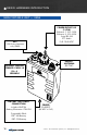
device hardware introduction man portable unit — Gen4 POWEr/Device i/o (19-pin) Ethernet 1: 10.3.1.254 Ethernet 2: 10.3.2.254 Serial RS-232 PTT Audio PoE: 10-48 VDC GPS 3.
device hardware introduction man portable unit — Gen3 SINGLE Radio 1 Antenna (RP-TNC) POWEr/Device i/o (19-pin) Ethernet 1: 10.3.1.254 Ethernet 2: 10.3.2.254 Serial RS-232 PTT Audio PoE: 10 - 48 VDC Auxiliary Power (3-Pin) 10-48 VDC pushbutton/led zeroize: press 3x in < 2 seconds gps 3.
device hardware introduction QUAD RADIO ROUTER Ethernet 2 switCh port (RJ45) CANNOT accept PoE Ethernet 2 IP: 10.3.2.
device hardware introduction gps 3.3V Active Antenna only (SMA) pushbutton/led zeroize: press 3x in < 2 seconds radio 4 Antenna (N-type) radio 3 Antenna (N-type) Ethernet 2 switCh port (rj45) CANNOT accept PoE Ethernet 2 IP: 10.3.2.254 POWER/Ethernet 1 (rj45) Accepts PoE, 10-48 VDC Ethernet 1 IP: 10.3.1.
device hardware introduction man portable unit — Gen3 DUAL Radio 1 Antenna (RP-TNC) POWEr/Device i/o (19-pin) Ethernet 1: 10.3.1.254 Ethernet 2: 10.3.2.254 Serial RS-232 PTT Audio PoE: 10 - 48 VDC Radio 2 Antenna (RP-TNC) Auxiliary Power (3-Pin) 10-48 VDC gps 3.
device hardware introduction AID Push-to-talk (ptt) audio (nato 6-pin connector) POWER/Ethernet 1 (rj45) Accepts PoE, 10-48 VDC Factory Setup IP: 10.3.1.254 © 2010 - 2015 Persistent Systems, LLC – All Rights Reserved Ethernet 2 (RJ45) PoE, 10-48 VDC Factory Setup IP: 10.3.2.
Device operation 16 © 2010 - 2015 Persistent Systems, LLC – All Rights Reserved
Device Operation Pushbutton/LED Operation Note: STATE LED STATUS OFF Operation Instruction ON/OFF Power OFF Boot Up (30s - 2 mins) HOLD (1 second) ON Fully Operational Zeroize ON Configuration Required SLOW BLINK tap 3 times (< 2 sec) Zeroize FAST BLINK Low Battery (MPU4 Only) OFF 2 SEC, ON .
Device Operation Configuration When a node is shipped from the factory, it is in a state that requires configuration. Nodes can be configured by using the Web Management Interface or through the Management API. Follow the steps under “Initial Node Configuration” to put the nodes into an operational state. The basic steps required to configure a node to an operational state are: SET ENCRYPTION KEY A key must be set in order for a node to communicate with other nodes in the network.
© 2010 - 2015 Persistent Systems, LLC – All Rights Reserved 19
web management overview 20 © 2010 - 2015 Persistent Systems, LLC – All Rights Reserved
web management overview web management introduction The Wave Relay® Web Management Interface enables users to configure and monitor Wave Relay® units through a web browser. A navigation bar organizes the Management Interface. The “Node Status” and “Node Configuration” tabs pertain only to the node to which the management computer is connected (either by Ethernet cable or by wireless), and the “Network Status” and “Network Configuration” tabs pertain to the entire network of nodes.
web management overview Accessing the Web Management Interface Node Connectivity Information Default Management Password Ethernet 1 Factory Setup IP Ethernet 2 Factory Setup IP Password 10.3.1.254 10.3.2.254 • Factory Setup IP addresses are always accessible when directly connected to the radio. Use Factory IPs any time you do not remember the management IP address of the radio.
web management overview Configuring Your Computer’s IP Address For your computer to be able to communicate with the Wave Relay®, it must have an IP address that is in the same IP subnet mask as the Wave Relay®’s IP address. A subnet mask of 255.255.255.0 means that the computer can communicate with another device that has an IP address matching the first three numbers of its own IP address. No Default Gateway or DNS server configuration is required; however they can be configured if necessary.
web management overview Security certificate warnings Recommended browsers are Firefox 3+, Internet Explorer 7+, and Google™ Chrome. Internet Explorer 6 is not compatible with the most recent Web Management Interface. If you are having difficulty connecting to the Web Management Interface, make sure you are using one of the recommended browsers. When connecting to the Web Management Interface, Firefox and Internet Explorer may ask the user to accept a security certificate.
web management overview Google™ Chrome displays a page 1. Click the “Proceed anyway” button. 2. When the Web Management Interface loads, enter the management password and click “Authenticate.” The default management password is “password” which is set from the factory or after the key/configuration is zeroized by pushing the on/off button 3 time in less than 2 seconds.
Initial node configuration 26 © 2010 - 2015 Persistent Systems, LLC – All Rights Reserved
Initial node configuration All nodes arrive set to factory default configuration. This section details the recommended setup and custom configuration procedure for a set of identical nodes, for example, a set of 50 MPU4s. In general, the procedure is completed as follows: 1. 2. 3. 4.
initial node configuration Step 1: Configure network defaults Network Defaults are settings that will be used to manage the configuration of the network. Up to 16 different default Channel settings are able to be configured. 1. 2. 3. Click “Network Configuration” > “Network Defaults.” Choose the settings you would like to use for your network for each Channel. Click the “Save to Network” button at the bottom of the page.
Initial node configuration STEP 3: CONFIGURE RADIO TO USE DEFAULTS The node must be configured to use the appropriate Network Defaults in order for the node to be managed by changes to the Network Configuration. 1. 2. 3. Click “Node Configuration” > “Node Configuration.” Select the appropriate Network Defaults in the drop down menus. Click the “Save & Reconfigure Unit” button at the bottom of the page. For more information, see section “Configuring Radio to Use Defaults.
initial node configuration 2 3 1 STEP 6: SET AND SAVE SECURITY SETTINGS A node will not function properly unless it has a valid key. If the “Security” tab in the Web Management Interface is blinking red, then a proper key has not been set. All nodes in a network must use the same Crypto Mode AND Key in order to communicate. 1. 2. 3. Select the “Security” tab in the Web Management Interface. Select a Crypto Mode to match your network requirements.
Initial node configuration 1 Enter your key here 2 Ensure all nodes are using the same Crypto Mode Click here after entering key 3 © 2010 - 2015 Persistent Systems, LLC – All Rights Reserved 31
initial node configuration Steps for configuring the remaining nodes STEps for COnfiguring the remaining nodes 32 1. Load Configuration File into All Other Nodes 2. Load Key into All Other Nodes 3. Verify Nodes are Communicating 4. Push Node List to Network 5.
Initial node configuration STEP 1: LOAD CONFIGURATION FILE INTO ALL OTHER NODES When setting up a network of new nodes from the factory, use the configuration file saved in the “Store Configuration File” step to upload the settings from the previously configured node into the new node. During this process, node specific settings (including IP Address, Radio Name, and other radio specific settings) can be configured separately for each node while preserving all other settings from the configuration file. 1.
initial node configuration STEP 3: VERIFY NODES ARE COMMUNICATING After nodes have been configured, the connectivity of the nodes should be checked. 1. 2. Ensure that all nodes are turned on, that at least one radio on each node has an antenna and is set to the same channel as the other nodes, and that each node has the same key. Access one of the nodes and verify connectivity to all the nodes. Click “Node Status” > “Neighbor Status.
Initial node configuration STEP 5: SET MANAGEMENT PASSWORD After all nodes have been configured, the management password should be changed. 1. 2. 3. 4. Click “Network Configuration” > “Network Password.” Enter the old password in the “Old Password” field. Enter the new password in both “New Password” fields. Click the “Change” button to change the management password. The management password will be changed on all nodes in the node list. The current node list is displayed at the bottom of the page.
initial node configuration node list The Node List contains a list of nodes specified by IP Address that are controlled by the Web Management Interface. Any function that resides under Network Status or Network Configuration operates on, and only on, the nodes listed in the node list. network vs managed nodes defined In the context of Wave Relay®, the network is defined as the set of nodes for which routing is possible. These nodes do not need to be specified in the Node List.
Initial node configuration network upgrade Network Upgrade installs new firmware versions on large numbers of nodes with one operation. Since network upgrades function on all nodes in the Node List, make sure the Node List is complete and current before performing a Network Upgrade. 1. 2. 3. 4. Click “Network Configuration” > “Network Upgrade.” Browse and select the appropriate upgrade file. Check or uncheck “Require All.
web management interface reference 38 © 2010 - 2015 Persistent Systems, LLC – All Rights Reserved
web management Interface Reference Node Status The “Node Status” tab in the Web Management Interface contains node-specific information for the individual node that the user is connected to.
web management Interface Reference UNIT INFO Unit Info displays a list of hardware and software information related to the node. menu item menu item Description Firmware Version Firmware version on node Serial No.
web management Interface Reference Neighbor Status Neighbor Status page displays a list of neighbor nodes that the current node has an RF connection with. If the neighbor node is in the node list and the “Update Network” operation has been performed, the node’s name, IP address, and radio interface will be displayed. Otherwise, the neighbor node’s MAC address will be displayed.
web management Interface Reference Gps status Position Update Status: menu item menu item Description Source GPS information source Latitude Latitude of current node Longitude Longitude of current node Altitude Altitude above sea level of current node System Clock Status: When the system clock was set by GPS Current system time Internal GPS Status: menu item menu item Description Fix Type How node is connected (3D, 2D, or none) Latitude Latitude of current node Longitude Longitude of curren
web management Interface Reference Traffic load Traffic load monitors and analyzes the trafffic load on the wireless and wired networking interfaces on the node.
web management Interface Reference bandwidth test Bandwidth Test is a tool for testing the data throughput from the node to another node in the network. It is recommended to perform at least a 5 second throughput test. Wave Relay® nodes run a TCP iPerf server. To perform a TCP throughput test through the iPerf server, use the command “iperf -c X” (X is the IP address of the node) from the command line. WARNING: Windows has known issues running iPerf and does not give true bandwidth readings.
web management Interface Reference Tracking status Tracking Status displays relevant antenna tracking status and diagnostic information.
web management Interface Reference ip flow list IP Flow List lists IP data flows passing through node sorted by measured throughput.
web management Interface Reference menu item menu item Description Gateway Which gateway the node is connected to as well as the priority of that gateway Elected Whether the gateway is elected or not Election Priority Election priority of the gateway over other gateways/number of other WRoIP gateways on the IP network.
web management Interface Reference NODE CONFIGURATION The “Node Configuration” tab in the Web Management Interface contains configuration options for managing an individual node. Click “Node Configuration” > “Node Configuration” to access basic Node Configuration settings.
web management Interface Reference Show/hide advanced fields For convenience, this button allows you to show (or hide) many of the less frequently used node configuration fields. The default is to hide the advanced fields (and thus display a briefer page). If you choose to show the advanced fields, your choice will remain in effect when you revisit the page. Advanced fields are indicated as such in the descriptions below.
web management Interface Reference Manet (advanced) menu item menu item Description IP Multicast Routing AUTO: Node will prune multicast packets that are not requested (default, most efficient setting for network). PULL ALL MULTICAST: Node will accept all multicast packets it hears on the network. Note: Windows CE/XP computers do not respond to IGMP Multicast Group Queries sent by Wave Relay nodes. “Pull All Multicast” should be used in networks with Windows CE/XP computers to work around this issue.
web management Interface Reference Frequency Each radio should be a assigned a frequency. Two radios must be set to the same frequency in order to communicate. If the radio is configured to use a “Network Default” channel, the radio’s channel assignment can be managed globally by clicking “Network Configuration” > “Network Defaults.” Ensure that the frequency is set to match the radio installed in the unit. A warning will be displayed if the frequency setting does not match the radio hardware.
web management Interface Reference access point settings (advanced) menu item menu item Description 802.11 Access Point (advanced) 2.4GHz and 5.8GHz radios can be configured to function as an 802.11 access point. Standard clients such as laptops with built in 802.11 cards may access this system. If the AP is disabled, the ESSID and Beacon Interval configuration options have no effect. For maximum performance, always disable the 802.11 AP unless it is required. To use a radio as a 802.
web management Interface Reference AP Beacon Interval (advanced) The 802.11 access point can send beacons at an interval between twice and ten times per second. VLAN ID (advanced) Each 802.11 AP is a VLAN-aware bridge port. Each port is assigned a VLAN ID. Untagged frames received by the port are tagged with the specified VLAN ID. Frames that are sent by the port which have a VLAN tag matching the specified VLAN ID will have their tags removed (i.e. they are sent by the port untagged).
web management Interface Reference VLAN Priority (advanced) Specifies the 802.11 priority of the VLAN tag added to untagged frames received by this port VLAN Trunking (advanced) Controls the filtering of VLAN tagged frames that do NOT match this port’s VLAN ID - Trunking enabled: ALL non-matching VLAN tagged frames are passed (no filtering). Trunking disabled: all non-matching VLAN tagged frames are blocked (filtered).
web management Interface Reference DHCP Server (advanced) If enabled, the DHCP server will serve IP addresses to devices connected to the node via the wired Ethernet or wireless 802.11 Access Point interfaces. menu item menu item Description DHCP Server Scope Selects which DHCP clients the DHCP server serves IP addresses to. “Local Ethernet/AP Only” serves IP addresses to nodes connected via Ethernet or a wireless 802.11 Access Point. “Entire Network” serves IP addresses to all nodes in the network.
web management Interface Reference Wave Relay® over ip (wroip) (advanced) WRoIP allows the Wave Relay® network to extend over and seamlessly interact with a large routed IP network. In order to use this capability, one or more Wave Relay® nodes must be setup as WRoIP gateways. A WRoIP gateway must be directly connected to an appropriately configured IP router.
web management Interface Reference NODE configuration for DLEP Dynamic Link Exchange Protocol (DLEP) (advanced): DLEP is used to transmit characteristics and metrics of the wireless network to a connected DLEP-capable router such as the Cisco 5915. This feature is available on all Wave Relay® versions. It supports DLEP Draft 00. The Wave Relay® MANET operates at Layer 2 of the OSI mode.
web management Interface Reference position The node’s position must be specified in order to provide data to the visualization, CoT, and tracking features. The position may be specified via internal or external GPS, manually, or from an external feed.
web management Interface Reference Latitude Allows the user to manually define the node’s latitude in decimal degrees (only visible in “Manual Entry” mode) Longitude Allows the user to manually define the node’s longitude in decimal degrees (only visible in “Manual Entry” mode) Altitude Allows the user to manually define the node’s altitude in feet above GPS ellipsoid - approximately equal to feet above mean sea level (MSL) (only visible in “Manual Entry” mode) External Update UDP Port Defines the p
web management Interface Reference Wave Relay® sa (Google™ earth network visualization) menu item menu item Description Report to Server Sending visualization updates can be individually enabled or disabled on each node. Setting “Network Default,” allows visualization to be turned on and off for the entire network at once via the Network Default configuration. Note that the selected server IP address is displayed here but is configured as part of the Network Default configuration.
web management Interface Reference CONFIGURATION MANAGEMENT A Master Configuration File allows the user to associate IP addresses, configuration files, and names with specific nodes. See RCT Tool Manul creating a master configuration file 1. Create a temporary directory in an easy to find location with a recognizable name. 2. Connect a node to the computer and set configuration as desired. 3. Click “Node Configuration” > “Config Management.” 4. Click the “Store” button.
web management Interface Reference uploading a master configuration file 1. Ensure all nodes in the Master Configuration File are in the node list. 2. Click “Node Configuration” > “Config Management.” 3. In the Load Configuration menu, select “network (require all)” or “network (any available)” to upload configuration settings to all nodes in the network. The “network (require all)” setting will require all nodes in the network be available for any changes to be applied.
web management Interface Reference Quick Setup Both “Load Configuration from File” and “Quick Setup” load configuration settings from a configuration file. The difference between the functions is that “Quick Setup” loads all the configuration settings from a file (except Node Identifiers), whereas “Load Configuration from File” loads user-selected configuration categories. Quick Setup facilitates the configuration of a large number of nodes when the nodes share identical configuration settings.
web management Interface Reference RESET TO FACTORY CONFIGURATION The Web Management Interface contains a “Reset to Factory Configuration” feature to remove all custom configuration and restore the node to its factory settings. 1. 2. 3. 64 Click “Node Configuration” > “Config Management.” Scroll to the bottom of the page. Resetting the node to its factory settings will remove all custom configuration and will reset the IP address to 10.4.1.254.
web management Interface Reference tracking antenna control For information on setting up the Tracking Antenna Control system hardware, please refer to the Tracking Antenna Manual. Tracking configuration To enable the tracking antenna control system, go to the “Node Configuration” tab and click on the “Tracking Configuration” button. On the drop down menu, select “Enabled” next to the Tracking Antenna Control option.
web management Interface Reference CoT UDP Port Defines the port number to receive coordinate updates via an external CoT feed CDF UDP Port Defines the port number to receive coordinate updates via an external CDF feed Compass Reading Specifies the heading of the Pan/Tilt unit - The heading is defined as the compass reading taken when standing behind the Pan/Tilt unit while facing the large circular electrical connector. For more information, see the compass reading step of the setup procedure.
web management Interface Reference push-to-talk (ptt) Push-to-Talk (PTT) voice is supported on all Wave Relay® nodes. By default, Wave Relay® supports single-channel PTT voice on a specified multicast IP address and port. You can “switch channels” by specifying an alternate IP address or port. Users can talk or listen (but cannot do both simultaneously). Transmissions from an individual user are broadcast to all other users on the network. Only one person can talk at a time.
web management Interface Reference Push-to-talk configuration menu item menu item Description Run PTT subsystem Enables or disables push-to-talk voice Volume Defines the default earpiece volume for headsets - Valid values are 0 through 125 (Values above 100 are digitally amplified) Microphone Level Defines the default microphone level for headsets - Valid values are 0 through 100 or “auto.” The “auto” configuration uses automatic gain control for microphone input and is recommended for most users.
web management Interface Reference channel definitions The Wave Relay® Network has 16 channels numbered 0 through 15. Channel 0 is the Flash Override Channel and has priority over channels 1-15. The Flash Override Channel will always be enabled and is capable of both receiving and transmitting audio. Channels 1-15 are normal audio channels. Audio channels 1-15 may be configured to be either Selected Channels or Monitored Channels.
web management Interface Reference Audible notifications menu item menu item Description Low Battery Enables or disables audible notification when the battery is depleted to 5% (notification will occur every 5 minutes) In-Net/Out-Net Enables or disables an audible notification when a chosen node enters or leaves the network Node to Monitor Selects a node to monitor for In-Net/Out-Net audible notifications from the node list (only visible when In-Net/Out-Net Audible Notifications are enabled) 70 ©
web management Interface Reference rs-232 The RS-232 serial-over-Ethernet feature can be used for remote control of a distant serial device via the Wave Relay® network. A typical application is for a local PC to control a distant pan/tilt camera via a serial link. If the PC and camera cannot be colocated, then two Wave Relay® devices can be used to connect them (similar to an old-fashioned modem-to-modem link).
web management Interface Reference Configuring Serial-to-Serial Mode 1. Connect the serial device to be controlled (e.g. pan/tilt unit) to the serial port on the distant Wave Relay® device. Configure the RS-232 Configuration Mode on the distant Wave Relay device to “Server” and set the Serial-over-Ethernet Port as desired. Set the Serial-over-Ethernet Protocol to “Raw.
web management Interface Reference Virtual-to-serial Mode Confirming Serial Connectivity Once you have configured the server and client as described above, the network connection status is displayed on the “Current Status” line. Statistics are displayed for transmitted and received bytes to/from the attached serial device, which can be used to debug the connection to your serial hardware.
web management Interface Reference rs-232 configuration menu item menu item Description Mode Disabled The serial-over-Ethernet feature is turned off. Server Use this mode when the device to be controlled (e.g. pan/tilt unit) is connected to a Wave Relay® device serial port. Client Use this mode when a controller (e.g. PC) is connected to a Wave Relay® device serial port.
web management Interface Reference Date/Time When possible, Wave Relay® will obtain the current date and time from its internal GPS hardware. However, in cases where the GPS is unlocked (or absent), you may alternatively specify an NTP server or manually set the current date and time. You may also set the local time zone. The default time zone is UTC (a.k.a. GMT or Zulu time). Note that some Wave Relay® device models do not contain a clock, and thus these settings may be unavailable.
web management Interface Reference date/time settings menu item menu item Description Current System Time Displays the current system time (in both UTC and current time zone if not UTC) Set local timezone Sets the local time zone as ±12 hours from UTC (settings also include select US and other global time zones) Manually set time Manually sets the current local time NTP Server Address Defines the address, if available, of the NTP (Network Time Protocol) server for automatic clock synchronization S
web management Interface Reference amplifier configuration Any Wave Relay® device (MPU4, MPU3 Single, MPU3 Dual, and Quad Radio Router) may be configured for use with an amplifier. To access Amplifier Configuration settings, select the “Node Configuration” tab, then click the “Amplifier Configuration” button. The page will display separate sections for each radio so that the amplifier settings for each radio may be configured separately.
web management Interface Reference Valid amplifier settings are: • WR-AMP-0900 900 MHz Amplifier • WR-AMP-1370 1.3 GHz Amplifier • WR-AMP-2400 2.3 - 2.5 GHz Amplifier When the Amplifier Configuration page for a QAMP device is accessed from the Web Management Interface, the sections for some radios may display the message “Amplifier Specified by Pelican Case.” The amplifier settings for these radios have already been configured.
web management Interface Reference network status The “Network Status” tab in the Web Management Interface displays information about every node in the node list. Each time a network status feature is used, all nodes in the node list will attempt to be contacted and the combined results will be displayed on one page. This feature is useful for managing a network without having to individually connect to each node. Refer to the “Node Status” section for more detailed information about a specific feature.
web management Interface Reference unit info menu item menu item Description Node Node name and IP address of each node in the network Uptime Operating time since last node power on or reboot Firmware Version Firmware version on node Temperature Temperature (in celsius) of node Supply Voltage Voltage supplied to node RCT Battery Voltage Voltage of real-time-clock keep-alive battery.
web management Interface Reference manet monitor MANET Monitor displays information about active nodes heard on the MANET.
web management Interface Reference GPS status menu item menu item Description Node Name and IP address of each node Result Fix Type How node is connected (3D, 2D, or none) Latitude Latitude of current node Longitude Longitude of current node Altitude Altitude above sea level of current node Speed Speed of node (m/s) in the horizontal plane Track Path of travel with respect to the Earth expressed in degrees - 000 degrees is North (angle increases clockwise through 360 degrees) Climb Speed o
web management Interface Reference Network Traffic Load menu item menu item Description Node Name and IP address of each node Result Mbps Total Total Mbps used on this interface Mbps Wave Relay® Total Mbps used by Wave Relay® Mbps Wave Relay® Sent Mbps used by Wave Relay® to send Mbps Wave Relay® Received Mbps used by Wave Relay® to receive Mbps Control Total Mbps used for control functions Mbps Control Ack Mbps used to control ACK Mbps Control RTS/CTS Mbps used to control RTS/CTS Mbps Oth
web management Interface Reference Network default check The Network Default Check page checks and displays which settings on each node are NOT set to the Network Default values. If a setting shows up in this list, it means that that particular setting on that node is NOT managed by Network Defaults and will NOT be changed if the Network Default is changed. network channel plan The Channel Plan page displays the channel center frequency and channel width for every radio of every node in the node list.
web management Interface Reference Station List The Station List page displays the list of 802.11 client stations connected to radios with 802.11 access point enabled for each node.
web management Interface Reference IP multicast status IP Multicast Status displays IGMP Snooping and IP Multicast Pruning status. This feature shows a table with a row for each multicast group, displaying an “F” if that group is forwarded over the MANET, or a “-” if it is not. There are known issues with IGMP in Windows XP. Attention: prior to fw version 18.4.0, Network will not function properly if pruning status is not consistent throughout the network.
web management Interface Reference network CONFIGURATION The “Network Configuration” tab contains options to manage the network node list, configure the network defaults, upgrade and reboot the network, and change the network password.
web management Interface Reference Network NODE LIST The Node List is a list of IP Addresses of nodes managed by the Web Management Interface. 1. 2. 3. 4. 88 To manage the Node List, click “Network Configuration” > “Network Node List.” Enter the IP Address of a node in the “Manually Add IP(s)” field and click the “Add” button to add the node associated with that IP Address to the Node List. Alternatively, nodes may be added from the “Other Nodes on Network” window if they are detected by the network.
web management Interface Reference NETWORK DEFAULTS Network Defaults facilitate the management of a large number of nodes. Network Defaults enable administrators to manage settings on all network nodes specified in the Node List rather than to manage individual settings on single nodes. Any changes to Network Defaults will affect only nodes that are in the Node List.
web management Interface Reference Radio Channel Settings Each radio must be a assigned a center frequency and bandwidth. These settings determine the “channel” on which the node operates. Up to 16 Network Default channel settings may be configured to facilitate management of groups of radios of different nodes. menu item menu item Description Channel Name Each channel can be assigned a name which to be used in status functions. Frequency Each radio should be a assigned a frequency.
web management Interface Reference Manet menu item menu item Description IP Multicast Routing AUTO: Node will prune multicast packets that are not requested (default, most efficient setting for network). PULL ALL MULTICAST: Node will accept all multicast packets it hears on the network. Note: Windows CE/XP computers do not respond to IGMP Multicast Group Queries sent by Wave Relay nodes. “Pull All Multicast” should be used in networks with Windows CE/XP computers to work around this issue.
web management Interface Reference Address Range Start Start of range of IP addresses assigned to DHCP clients Address Range End End of range of IP addresses assigned to DHCP clients Netmask Netmask assigned to DHCP clients Default Gateway Gateway assigned to DHCP clients DNS Server 1 Primary DNS server assigned to DHCP clients DNS Server 2 Secondary DNS server assigned to DHCP clients WINS Server WINS server assigned to DHCP clients Lease Time DHCP lease time (defaults to 1 hour) ACCESs poi
web management Interface Reference WPA2 Passphrase (advanced) Sets a shared passphrase when AP Security is set to WPA2 - The passphrase should be an ASCII string of length 8-63 characters, excluding these characters: ‘,”\&/<> AP Broadcast Rate (advanced) Controls the rate at which broadcasts are transmitted from an 802.11 Access Point - Increasing this rate can significantly increase network capacity but will reduce the range of client connectivity.
web management Interface Reference bandwidth management settings (advanced) menu item menu item Description IP Mcast/ Bcast Limit (advanced) Defines the maximum bandwidth allowed for IP multicast or broadcast network traffic received on the given interface and retransmitted onto the Wave Relay® network. Traffic in excess of this limit will be dropped. Units are megabits/sec (Mbps).
web management Interface Reference MTU (advanced) Defines the maximum transmissible unit size for the IP network - WRoIP protocol packets sent over the IP network will be limited to this MTU. All nodes that communicate over the IP network should be set to the same value. Multicast Address (advanced) Defines the multicast IP address used by the WRoIP protocol - The next higher IP multicast address will also be used by the WRoIP protocol. For example, if 239.255.90.
web management Interface Reference Visualization Server (advanced) Defines the IP address to which nodes will send their visualization updates (may be either a multicast address [224.0.0.0,239.255.255.255] or the unicast address of a device running the visualization server.) - The factory default is a multicast address. When using multicast, each node sends visualization updates to the entire connected network. All nodes run a visualization server and receive updates from all other connected nodes.
web management Interface Reference PTT Settings menu item menu item Description Enable Push-toTalk Enables or disables the PTT subsystem to allow push-to-talk communication among voice-equipped devices Volume Defines the default earpiece volume for headsets - Valid values are 0 through 100. Optimal values vary with headset manufacturer. Microphone Level Defines the default microphone level for headsets - Valid values are 0 through 100. Optimal values vary with headset manufacturer.
web management Interface Reference menu item menu item Description Channel Displays the channel number to be configured Name Defines the text name of the channel Multicast Address Defines the Multicast Address for the channel Valid values are within the range of 224.0.0.0 through 239.255.255.255. Note that each talk group must have a unique multicast address and port. Multicast Port Defines the Multicast UDP port for audio traffic - Valid values are within the range of 1 through 65534.
web management Interface Reference rs-232 Settings (advanced) The RS-232 serial-over-Ethernet feature can be used for remote control of a distant serial device via the Wave Relay® network. A typical application is for a PC to control a remotely located pan/tilt camera via a serial link. Two operational modes are supported: “serial-to-serial” mode and “virtual-to-serial” mode. For further description, see RS-232 Configuration Help.
web management Interface Reference date/time settings menu item menu item Description Set local timezone Sets the local time zone as ±12 hours from UTC (settings also include select US and other global time zones) NTP Server Address Defines the address, if available, of the NTP (Network Time Protocol) server for automatic clock synchronization Automatic powerdown/powerup One time only Instructs nodes to perform a one-time power down and power up at specified times as set in the Set powerdown time an
web management Interface Reference Save to Network Two check boxes are checked by default. Reconfigure immediately forces the network to apply the new settings and reboot immediately. Require all ensures all nodes in the managed node list receive the updated values or all will fail and not update. SECURITY status The Status box indicates the current security configuration. “Operational” means a valid key is set and Wave Relay® is operational.
web management Interface Reference “Error: no security configuration” will be displayed if a node is booted without a key set. An error will also be displayed if the key has been zeroized (see below). The current key, if one is set, can be viewed by selecting “Display Key.” Since the key is displayed in plaintext, view the key in a secure environment only. The “Display Key” feature indicates the current Crypto Mode, Size, and Value of the key.
web management Interface Reference 3. select the “Backwards Compatible: 256-bit AES-CTR with HMAC-SHA-1” mode on the units with newer hardware; this will allow all the nodes in the network to communicate. If you have a network with only newer hardware you can select any of the three modes. We recommend “256-bit AES-CTR with HMACSHA-512” as the mode with the greatest security margin. “256-bit AES-GCM” is an alternate full Suite-B mode that can also be used based on user preference.
web management Interface Reference WAVE RELAY® API The Wave Relay® router provides an API for configuring and monitoring the radio outside of the management interface. The API runs over the on-board HTTPS interface, allowing any program or package that submits requests according to the HTTP protocol (RFC 2616) to communicate with the Wave Relay®. Some example programs include custom programs written in Java or C/C++ as well as the Linux “Curl” command.
web management Interface Reference © 2010 - 2015 Persistent Systems, LLC – All Rights Reserved 105
troubleshooting 106 © 2010 - 2015 Persistent Systems, LLC – All Rights Reserved
troubleshooting Common problems and troubleshooting This section contains a list of troubleshooting steps to follow when two or more nodes are unable to communicate. The following must be configured correctly for Wave Relay® nodes to communicate: 1. Encryption Key and Type 2. Radio Enabled 3. Channel Frequency and Channel Width 4. Firmware Version 5. Mesh Routing Enabled 6.
Troubleshooting symptom Potential root cause potential solution Nodes are unable to communicate nodes not powered on 1. Check for depleted batteries and/or disconnected power cables. Inadequate power supply 1. MPU3/MPU4 can require as much as 18W of peak power to operate. Quads (with 2W radio) can require as much as 60W. Ensure that 60W PoE injector is being used. Ensure other power sources are adequate. 2. 3. crypto mode and/or crypto key set incorrectly 1. 2. 3. Radios Not Enabled 1. 2.
troubleshooting Max Link Distance Set Incorrectly 1. 2. 3. Incompatible Firmware Versions 1. 2. Mesh Routing Disabled 1. 2. Antenna Connected to Wrong Radio 1. © 2010 - 2015 Persistent Systems, LLC – All Rights Reserved Radios are able to communicate when set to different link distances but will result in suboptimal performance. To set Max Link Distance correctly, determine the farthest distance any individual link on this frequency may need to be, then choose the next longest Max Link Distance.
Troubleshooting Poor/low throughput RF Interference 1. 2. 3. Poor audio 110 As a general rule of thumb, if there is no RF interference and nodes are in proximity to each other, a 20MHz channel should observe approximately 20Mbps throughput, a 10MHz channel should observe approximately 10Mbps, and a 5MHz channel should observe approximately 5Mbps. If low throughput is measured, test other center frequencies until you achieve the highest throughput possible for a given channel width.
troubleshooting Multicast traffic stops after a few seconds Pruning Status Set Incorrectly (FW versions 18.3.x and earlier only) 1. Client Device is Using Windows CE/XP 1. 2. 2. 3. © 2010 - 2015 Persistent Systems, LLC – All Rights Reserved Prior to FW version 18.4.0, if pruning status is not the same on all nodes in the network, then multicast traffic will not forward properly. To check Pruning status, click “Network Status” > “IP Multicast Status.
Hardware Details 112 © 2010 - 2015 Persistent Systems, LLC – All Rights Reserved
Hardware details © 2010 - 2015 Persistent Systems, LLC – All Rights Reserved 113
man portable unit — Gen4 114 © 2010 - 2015 Persistent Systems, LLC – All Rights Reserved
© 2010 - 2015 Persistent Systems, LLC – All Rights Reserved 115
Hardware details man portable unit — Gen4 Headset & Push-To-Talk Adapter WR-ACC-067 6-pin to Micro USB Adapter Cable CBL-117 Audio Options 19-Pin to 6-Pin Connector CBL-115 GPS Stub Antenna WR-ANT-071 MAN PORTABLE UNIT 4 WR-MPU4-XX Android™Smart EUD Android™ Phone 6-Pin Connectors CBL-116 CBL-118 Battery BAT-06 (Included with WR-MPU4-XX) Samsung™ Galaxy Note Ruggedized Enclosure MOLLE-IP67-NOTE 116 © 2010 - 2015 Persistent Systems, LLC – All Rights Reserved
hardware details CASE & POUCH OPTIONS SOC PINS 1-4 0 (1) SOC PINS - 12V 2-5 (2) + (5) SW (6) 100 (3) + 12V (4) BA-2557 Pouch MOLLE-BA-2557 BA-2590 Pouch MOLLE-BA2590 PULL TO REVEAL SMB HighPerformance Ground-to-Air WR-ANT-059 2.3 - 2.5 GHz DO NOT USE IN JAVELIN MPU4 Pouch MOLLE-MPU4-2 Transit Case CASE-017 Springbase Adapter CBL-085 Battery BAT-06 Battery Charging Adapter BAT-07 Antenna Options 760 - 780 MHz WR-ANT-051 902 - 928 MHz WR-ANT-073 2.3 - 2.5 GHz WR-ANT-053 5.1 - 5.
Hardware details I/O connection - Mpu4 Pin Description 1 Ethernet 2 RXN (RJ45 pin 6) 2 Ethernet 2 TXN (RJ45 pin 2) 3 Audio GND 4 Ethernet 1 RXP (RJ45 pin 3) 5 Ethernet 2 RXP (RJ45 pin 3) 6 Ethernet 2 TXP (RJ45 pin 1) 7 Audio Input (Microphone) 8 Ethernet 1 TXN (RJ45 pin 2) 9 Ethernet 1 RXN (RJ45 pin 6) 10 GPIO 11 Audio PTT or RS-232 WR Tx/Dev Rx 12 Audio Output (Speaker) 13 Ethernet 1 TXP (RJ45 pin 1) 14 Power GND 15 RS-232 Wave Relay® Rx/Device Tx 16 +5V Accessory Power (1 Amp Max) 17 3.
Hardware Details PTT Audio - MPU4 Aid NOTE The PTT Audio connections for the MPU4 is not wired the same as the MPU3 or Quad Radio Router.
Hardware details battery twist-lock connection - Mpu4 Power specifications Voltage Range: 8-30 VDC Pin Description Center Smart I/O Outer Power Flange Ground What to Connect Included: BAT-06 Battery Eliminator: CBL-054 Compatible With: PRC-148 Thales MBITR Battery PRC-152 Harris Falcon III Battery 120 Connector Information • IP67 Rated • Used to power an MPU4 when not using 19-pin I/O PoE functionality © 2010 - 2015 Persistent Systems, LLC – All Rights Reserved
Hardware Details © 2010 - 2015 Persistent Systems, LLC – All Rights Reserved 121
man portable unit — Gen3 122 © 2010 - 2015 Persistent Systems, LLC – All Rights Reserved
© 2010 - 2015 Persistent Systems, LLC – All Rights Reserved 123
Hardware details man portable unit — Gen3 POWER OPTIONS To Power - 8-48V DC Input BA-2590 BAT-02 BA-2557 BAT-08 PULL TO REVEAL SMB SOC PINS 1-4 0 (1) SOC PINS - 12V 2-5 (2) Antenna Options + (5) SW (6) 100 + 12V (4) (3) DO NOT USE IN JAVELIN BATTERY CHARGING ADAPTER BAT-03 HighPerformance Ground-to-Air WR-ANT-059 2.3 - 2.
hardware details Computer GPS Antenna WR-ANT-040 (2 foot cable) WR-ANT-040L (10 foot cable) 19-Pin to Ethernet Cable CBL-043 Standard Ethernet Cable CBL-046 19-Pin to 19-Pin Cable CBL-035 (Standard) CBL-098 (Ultra Flexible) Auxiliary Input Device (AID) WR-AID-01 Camera MAN PORTABLE UNIT 3 With One Radio: WR-MPU3-XX With Two Radios: WR-MPU3-XXXX © 2010 - 2015 Persistent Systems, LLC – All Rights Reserved Headset & Push-ToTalk Adapter WR-ACC-067 Audio Options 125
Hardware details I/O connection - Mpu3 Pin Description 1 Ethernet 2 RXN (RJ45 pin 6) 2 Ethernet 2 TXN (RJ45 pin 2) 3 Audio GND 4 Ethernet 1 RXP (RJ45 pin 3) 5 Ethernet 2 RXP (RJ45 pin 3) 6 Ethernet 2 TXP (RJ45 pin 1) 7 Audio Input (Microphone) 8 Ethernet 1 TXN (RJ45 pin 2) 9 Ethernet 1 RXN (RJ45 pin 6) 10 N/C 11 Audio PTT 12 Audio Output (Speaker) 13 Ethernet 1 TXP (RJ45 pin 1) 14 Power GND 15 Wave Relay® Tx/Device Rx 16 RS-232 Wave Relay® Rx/Dev Tx or +5V Accessory Power (1 Amp Max) 17 3.
Hardware Details PTT AUDIO - MPU3 AID NOTE The PTT Audio connections on the MPU3 and the MPU4 are NOT wired identically.
Hardware details Auxiliary Power - MPU3 Power specifications Voltage Range: 8-48 VDC Maximum Current: 5 Amps A B C Pin Description A Ground B Power IN C N/C Connector Information • Glenair 801 Series “Mighty Mouse” Connector • IP67 Rated in the Mated State • Used to power an MPU3 when not utilizing the 19pin I/O PoE fuction What to Connect CBL-037, 045 → PWR to BA-2557, BA-2590, BA-5590 CBL-059 → PWR to Vehicle DC Power Port 128 © 2010 - 2015 Persistent Systems, LLC – All Rights Reserved
Hardware Details © 2010 - 2015 Persistent Systems, LLC – All Rights Reserved 129
Quad Radio Router 130 © 2010 - 2015 Persistent Systems, LLC – All Rights Reserved
© 2010 - 2015 Persistent Systems, LLC – All Rights Reserved 131
Hardware details Quad Radio Router MOUNTING OPTIONS 220 VAC 4-Pin to RS-232 CBL-060 (Male) CBL-061 (Female) 110 VAC Mag Mount Bracket WR-ACC-010 PoE Injector WR-PWR-48V - 60W (Included free) 4-Pin to 4-Pin CBL-034 RF Cable CBL-030 Antenna Magnetic Mount WR-ACC-013 BA-2590 BAT-02 4-Pin to Car Adapter CBL-062 BA-2557 BAT-08 PULL TO REVEAL SMB SOC PINS 1-4 0 (1) SOC PINS - 12V 2-5 (2) + (5) SW (6) 100 (3) + 12V (4) DO NOT USE IN JAVELIN BATTERY CHARGING ADAPTER 4-Pin to BA CBL-029 Cable
hardware details 5 GHz WR-ANT-026 2.
Hardware details sector array kit MOUNTING OPTIONS 4-Pin to RS-232 CBL-060 (Male) CBL-061 (Female) Heavy Duty Tripod WR-ACC-034 (15 meters) WR-ACC-028 (7 meters) BA-2590 BAT-02 4-Pin to 4-Pin CBL-034 BA-2557 BAT-08 PULL TO REVEAL SMB SOC PINS 1-4 0 (1) SOC PINS - 12V 2-5 (2) + (5) SW (6) 100 (3) + 12V (4) DO NOT USE IN JAVELIN BATTERY CHARGING ADAPTER BAT-04 4-Pin to Car Adapter CBL-062 4-Pin to BA CBL-029 Cable Options BAT-03 To Power Battery Charger BAT-05 (fits 4 Battery Charging
hardware details Antenna Options 2.
Hardware details tracker antenna system Outdoor PoE Injector WR-PWR-48V - 60W (US, EU, UK) 5GHz WR-ANT-026 BA-2590 BAT-02 2.
hardware details Amplified Speaker Kit WR-ACC-079 Tracking Antenna System TRK-KIT-06 Includes: - 2.
Hardware details Ethernet 1 ports - Quad radio router Poe Information Ethernet 1 Accepts 8-48 VDC Any standard Ethernet cable will carry power and date 1 8 Pin Description 1 Tx(+) 2 Tx(-) 3 Rx(+) 4 PoE Power 5 PoE Power 6 Rx(-) 7 PoE Ground 8 PoE Ground Connection Information • Standard CAT5e/RJ45 Ethernet Connection • Supports Power-Over-Ethernet PoE • Ethernet 1 Factory Setup IP Address: 10.3.1.254 • Receptacle is rated to IP67 in the unmated state.
Hardware Details Ethernet 2 Ports - Quad Radio Router WARNING Ethernet ports 2-5 do NOT support PowerOver-Ethernet Functionality 1 Pin Description 8 1 Tx(+) 2 Tx(-) 3 Rx(+) 4 N/C 5 N/C 6 Rx(-) 7 N/C 8 N/C Connection Information • Standard CAT5e/RJ45 Ethernet Connection • Ethernet 2 Factory Setup IP Address: 10.3.2.254 • Receptacle is rated to IP67 in the unmated state.
Hardware details Auxiliary power - Quad Radio Router Power specifications Voltage Range: 8-48 VDC Maximum Current: 5 Amps Pin Description A Power In B Ground C RS-232 Wave Relay® Tx/Dev Rx D RS-232 Wave Relay® Rx/Dev Tx Connector Information • IP67 Rated • Offers auxiliary power option and serial I/O • Mating Plug: CONN-046 What to Connect CBL-029, 062, 069, 034, 060, 061 140 © 2010 - 2015 Persistent Systems, LLC – All Rights Reserved
Hardware Details PTT Audio = Quad Radio Router NOTE The PTT Audio connections on the Quad Radio Router and the MPU4 are NOT wired identically.
Regulatory information Regulatory Information The following notes refer to these part numbers: WR-MPU4-04, WR-MPU3-04, WR-MPU3-0409, and WR-RTR2-04040909. This device complies with part 15 of the Fcc rules. Operation is subject to the following two conditions: (1) This device may not cause harmful interference, and (2) this device must accept any interference received, including interference that may cause undesired operation.
regulatory information © 2010 - 2015 Persistent Systems, LLC – All Rights Reserved 143
WAVE RELAY® USER MANUAL 03EN009 (English) VERSION 3.1 303 Fifth Avenue Suite 306 New York, NY 10016 www.persistentsystems.