Operating System for Ubiquiti M Series Products Release Version: 5.5.
airOS™ v5.5.4 User Guide Table of Contents Table of Contents Chapter 1: Overview. . . . . . . . . . . . . . . . . . . . . . . . . . . . . . . . . . . . . . . . . . . . . . . . 1 Introduction. . . . . . . . . . . . . . . . . . . . . . . . . . . . . . . . . . . . . . . . . . . . . . . . . . . . . . . . . . . . . . . . . . . . . . 1 Supported Products. . . . . . . . . . . . . . . . . . . . . . . . . . . . . . . . . . . . . . . . . . . . . . . . . . . . . . . . . . . . . . 1 airOS v5.5.4 Network Modes. . .
airOS™ v5.5.4 User Guide Table of Contents Chapter 7: Services Tab . . . . . . . . . . . . . . . . . . . . . . . . . . . . . . . . . . . . . . . . . . . 52 Ping Watchdog. . . . . . . . . . . . . . . . . . . . . . . . . . . . . . . . . . . . . . . . . . . . . . . . . . . . . . . . . . . . . . . . . . 52 SNMP Agent. . . . . . . . . . . . . . . . . . . . . . . . . . . . . . . . . . . . . . . . . . . . . . . . . . . . . . . . . . . . . . . . . . . . .53 Telnet Server. . . . . . . . . . . . . . . . . . . . .
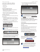
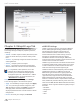
airOS™ v5.5.4 User Guide Chapter 1: Overview Chapter 1: Overview Supported Products Introduction airOS v5.5.4 supports the M Series product versions, including the following: • Rocket™M Welcome to airOS™ v5.5.4 – the latest evolution of the airOS Configuration Interface by Ubiquiti Networks™. airOS v5.5.
airOS™ v5.5.4 User Guide airOS v5.5.4 Wireless Modes airOS supports the following wireless modes: • Access Point Chapter 1: Overview 4. Upon subsequent login, the standard login screen appears. Enter ubnt in the Username and Password fields, and click Login. • Station / Client • AP-Repeater System Requirements • Microsoft Windows XP, Windows Vista, Windows 7, Windows 8, Linux, or Mac OS X • Java Runtime Environment 1.
airOS™ v5.5.4 User Guide Chapter 1: Overview Navigation The airOS Configuration Interface contains seven main tabs, each of which provides a web-based management page to configure a specific aspect of the Ubiquiti device: • Ubiquiti Logo The “Ubiquiti Logo Tab” on page 4 controls Ubiquiti’s proprietary technologies, such as airMAX, airView, airSelect, and airSync (GPS Series devices only). Note: By default, indoor products, such as the airRouter, do not display the Ubiquiti logo tab.
airOS™ v5.5.4 User Guide Chapter 2: Ubiquiti Logo Tab The Ubiquiti logo tab displays settings to enable, launch, and change settings for Ubiquiti’s proprietary features, including: • airMAX™ Provides superior wireless performance, more clients per Access Point (AP), and lower latency under load. • airSelect™ Dynamically changes the wireless channel to avoid interference. • airView™ Ubiquiti’s spectrum analyzer.
airOS™ v5.5.4 User Guide Chapter 2: Ubiquiti Logo Tab By default, all traffic is classified as Best Effort, so no prioritization is applied. The categories can be defined using the following values: 802.
airOS™ v5.5.4 User Guide • Frequency List Available when airSelect is enabled. Click Edit to select the frequencies that the AP will use for airSelect. Available frequencies are devicedependent. Chapter 2: Ubiquiti Logo Tab • Launch airView Click Launch airView to download the Java Network Launch Protocol (jnlp) file and complete the launch of airView. • Hop Interval Available when airSelect is enabled. The duration (in milliseconds) that the AP will stay on one frequency before moving to the next.
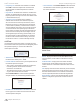
airOS™ v5.5.4 User Guide File Menu Chapter 2: Ubiquiti Logo Tab Charts Click Exit to end the airView session. View Menu Enable Chart Panel 1 (top) Displays the Waterfall or Channel Usage chart in Chart Panel 1, depending on which option you have selected in Preferences. This time‑based graph shows the aggregate energy collected or channel usage for each frequency since the start of the airView session. Enable Chart Panel 2 (middle) Displays the Waveform chart in Chart Panel 2.
airOS™ v5.5.4 User Guide Enable Real-time chart (bottom) Check the box to enable the bottom chart. This graph displays a traditional spectrum analyzer in which energy (in dBm) is shown in real time as a function of frequency. There are three traces in this view: • Current (Yellow) Shows the real-time energy seen by the device as a function of frequency. • Average (Green) Shows the running average energy across frequency. • Maximum (Blue) Shows updates and maximum power levels across frequency.
airOS™ v5.5.4 User Guide We have the following examples: • Four APs Use two different frequencies. Set the same frequency on each back-to-back pair of APs (this is the ABAB channel design). For example, a client is located equidistant from two APs (one set to frequency A and one set to frequency B). The client will only receive signals from the AP that shares its frequency. Chapter 2: Ubiquiti Logo Tab After you configure these durations, or slots, on the master AP, they are passed along to all slave APs.
airOS™ v5.5.4 User Guide Chapter 3: Main Tab The Main tab displays a summary of the link status information, current values of the basic configuration settings (depending on the operating mode), network settings and information, and traffic statistics. Status Device Name Displays the customizable name or identifier of the device. The Device Name (also known as host name) is displayed in registration screens and discovery tools. Ubiquiti Networks, Inc.
airOS™ v5.5.4 User Guide SSID Displays the wireless network name (SSID). The wireless network name depends upon the wireless mode selected: • In Station mode, this displays the SSID of the AP the device is associated with. • In Access Point mode, this displays the SSID configured on the device using the Wireless tab. Security Displays the wireless security method being used on the device. If None is displayed, then wireless security has been disabled, although you can still use RADIUS MAC authentication.
airOS™ v5.5.4 User Guide Chapter 3: Main Tab TX Rate/RX Rate (Available in Station mode only.) Displays the current 802.11 data transmission (TX) and data reception (RX) rates. airSelect Indicates the airSelect status. If airSelect is enabled, airSync is not available. Access airSelect setup through the Ubiquiti Logo tab > airSelect. airMAX Indicates the airMAX status. If airMAX is enabled, the device will only accept airMAX clients. airMAX also features advanced QoS autodetection settings.
airOS™ v5.5.4 User Guide Chapter 3: Main Tab Stations Station Information (Available in Access Point or AP‑Repeater mode only.) This selection lists the stations that are connected to the device. Detailed information is displayed when you click a specific MAC address: The following statistics for each station are displayed in the station statistics window: Station MAC Displays the MAC address of the station. This is a clickable link that will display additional station information.
airOS™ v5.5.4 User Guide Chapter 3: Main Tab • airMAX Capacity This is an index of the maximum data rate the link is operating at. A lower capacity number indicates a unit that is slowing down the system. Connection Time Displays the amount of time the device has been connected to the AP. The time is expressed in days, hours, minutes, and seconds. • Last IP Displays the station’s last IP address. Signal Strength The value represents, in dBm, the last received wireless signal level.
airOS™ v5.5.4 User Guide RX Bytes Displays the total amount of data (in bytes) received by the interface. RX Errors Displays the number of receive errors. TX Bytes Displays the total amount of data (in bytes) transmitted by the interface. TX Errors Displays the number of transmit errors. Refresh To update the information, click Refresh. DHCP Client (Available in Router or SOHO Router mode only.
airOS™ v5.5.4 User Guide Chapter 3: Main Tab Routes Port Forward Lists all the entries in the system routing table. (Available in Router or SOHO Router mode only.) Port forwarding allows you to connect to a specific service such as an FTP server or web server. Port forwarding creates a transparent tunnel through a firewall/NAT, granting access from the WAN side to the specific network service running on the LAN side.
airOS™ v5.5.4 User Guide Chapter 3: Main Tab GPS Details (GPS Series Only) GPS Details (available on GPS Series devices only) displays GPS Satellite details and Signal quality. Refresh To update the information, click Refresh. Log When logging is enabled (see “System Log” on page 55 to enable logging), this option lists all registered system events. By default, logging is not enabled. Clear To delete all entries in the system log, click Clear. Refresh To update the log content, click Refresh.
airOS™ v5.5.4 User Guide Chapter 4: Wireless Tab Chapter 4: Wireless Tab Change To save or test your changes, click Change. The Wireless tab contains everything needed to set up the wireless part of the link. This includes SSID, channel and frequency settings, device mode, data rates, and wireless security. • Apply To immediately save your changes, click Apply. A new message appears. You have three options: • Test To try the changes without saving them, click Test. To keep the changes, click Apply.
airOS™ v5.5.4 User Guide Basic Wireless Settings In this section, configure the basic wireless settings, such as wireless mode, wireless network name (SSID), country code, 802.11 mode, output power, and data rates. Wireless Mode Specify the Wireless Mode of the device. The mode depends on the network topology requirements. airOS supports the following modes: • Station If you have a client device to connect to an AP, configure the client device as Station mode.
airOS™ v5.5.4 User Guide Chapter 4: Wireless Tab Lock to AP MAC (Available in Station mode only.) This allows the station to always maintain a connection to an AP with a specific MAC address. This is useful as sometimes there can be multiple APs using the same SSID. Enter a MAC address in the Lock to AP MAC field, and the station will lock to the AP with this specific MAC address and not roam between several APs with the same SSID.
airOS™ v5.5.4 User Guide Channel Shifting Enables special channels with a frequency offset regarding standard 802.11b/g/n and 802.11a channels. This is a proprietary feature developed by Ubiquiti Networks. While 802.11 networks have standard channels (for example, Channel 36 (5180 MHz), Channel 40 (5200 MHz), and so forth, spaced every 5 MHz apart), channel shifting uses non-standard (non‑802.11) channels offset from the standard channels. All the channels can be shifted by 5 MHz (in 802.
airOS™ v5.5.4 User Guide Chapter 4: Wireless Tab Antenna Gain (Only applicable to devices with external antenna connectors.) Enter the antenna gain in dBi. With Auto Adjust to EIRP Limit enabled, Antenna Gain calculates the TX power backoff needed to remain in compliance with local regulations. The Antenna Gain setting complements the Cable Loss setting; they both affect the TX power of the device. Wireless Security Cable Loss (Only applicable to devices with external antenna connectors.
airOS™ v5.5.4 User Guide None Chapter 4: Wireless Tab WEP Authentication Type Select one of the following authentication methods: RADIUS MAC Authentication You can authenticate devices using their MAC addresses. MAC Format Select the appropriate format of the MAC address. Use Empty Password To submit the MAC address without a password, check the Enable box. Auth Server IP/Port In the first field, enter the IP address of the RADIUS authentication server.
airOS™ v5.5.4 User Guide WPA or WPA2 The configuration options are the same for all of the WPA and WPA2 options. WPA2-AES is the strongest security method. If all of the wireless devices on your network support this option, we recommend that you select it. Chapter 4: Wireless Tab WPA User Password Enter the password credential used by the supplicant for EAP authentication. Show Check the box if you want to view the characters of the WPA User Password.
airOS™ v5.5.4 User Guide Chapter 4: Wireless Tab MAC ACL The options below apply in Access Point or AP‑Repeater mode only. MAC ACL The MAC address Access Control List (ACL) lets you allow or deny clients connectivity to the device. When enabled, you have the following options: Policy Select one of the policy types: • Allow Wireless clients on the list can access the device. Any wireless client that is not on the list is denied access to the device.
airOS™ v5.5.4 User Guide Chapter 5: Network Tab The Network tab allows you to configure bridge or routing functionality and IP settings. Change To save or test your changes, click Change. A new message appears. You have three options: • Apply To immediately save your changes, click Apply. • Test To try the changes without saving them, click Test. To keep the changes, click Apply.
airOS™ v5.5.4 User Guide Chapter 5: Network Tab The following diagram shows the NanoStation at a residence wirelessly connecting to a WISP tower. WISP Tower Disable Network Disables the WLAN, LAN, or WAN interface(s). Use this setting with caution as you cannot establish any Layer 2 or Layer 3 connection through the disabled interface. You cannot access the device from the wireless or wired network that is connected to the disabled interface.
airOS™ v5.5.4 User Guide Management Network Settings Management Interface (Available in Advanced view.) Select the interface used for management. Management IP Address The device can use a static IP address or obtain an IP address from its DHCP server. • DHCP The local DHCP server assigns a dynamic IP address, gateway IP address, and DNS address to the device. Chapter 5: Network Tab -- Gateway IP Typically, this is the IP address of the host router, which provides the point of connection to the Internet.
airOS™ v5.5.4 User Guide Chapter 5: Network Tab Interfaces VLAN Network (Available in Advanced view.) The Maximum Transmission Unit (MTU) is the maximum packet size (in bytes) that a network can transmit. You can configure a different MTU for each of the interfaces. (Available in Advanced view.) You can create multiple Virtual Local Area Networks (VLANs). Click the + button to display the VLAN Network section. Click the + button to display the Interfaces section. Enabled Enables the specific VLAN.
airOS™ v5.5.4 User Guide If enabled, the device bridge communicates with other network devices by sending and receiving Bridge Protocol Data Units (BPDU). STP should be disabled (default setting) when the device is the only bridge on the LAN or when there are no loops in the topology, as there is no need for the bridge to use STP in this case. Ports Select the appropriate ports for your bridge network. (Virtual ports are available if you have created VLANs.) • Add Select a port. • Del Delete a port.
airOS™ v5.5.4 User Guide Chapter 5: Network Tab Traffic Shaping Egress (Available in Advanced view.) Traffic Shaping controls bandwidth from the perspective of the client (who is connected on the Ethernet interface). Bursting allows fast downloads when a user downloads small files (for example, viewing different pages of a website), but prevents a user from using excessive bandwidth when downloading large files (for example, streaming a movie). • Enable Enables the egress values.
airOS™ v5.5.4 User Guide Chapter 5: Network Tab Configuration Mode DHCP The Network tab has two views, Simple and Advanced. The external DHCP server assigns a dynamic IP address, gateway IP address, and DNS address to the device. Simple Displays the basic configuration settings: • “WAN Network Settings” on page 32 • “LAN Network Settings” on page 35 • “Port Forwarding” on page 38 • “Multicast Routing Settings” on page 39 Advanced configuration settings are hidden.
airOS™ v5.5.4 User Guide • DMZ Management Ports The web management port (TCP/IP port 80 by default) of the airOS device will be used for the host device. The airOS device responds to requests from the external network as if it were the host device that is specified with the DMZ IP address. DMZ Management Ports is disabled by default; the device is accessible from the WAN port.
airOS™ v5.5.4 User Guide • NAT Protocol If NAT is enabled, you can modify data packets to allow them to pass through the device. To avoid modification of some specific types of packets, such as SIP, PPTP, FTP, or RTSP, then uncheck the respective box(es). Block management access To block device management from the WAN interface, check this box. This feature makes Router mode more secure if the device has a public IP address.
airOS™ v5.5.4 User Guide Encryption Enables the use of Microsoft Point-to-Point Encryption (MPPE). NAT Network Address Translation (NAT) enables packets to be sent from the external network (WAN) to the local interface IP address and then sub-routed to other client devices on its local network while the airOS device is operating in Access Point or AP‑Repeater mode. Packets are routed in the reverse direction in Station mode. NAT is implemented using the masquerade type firewall rules.
airOS™ v5.5.4 User Guide • Disabled The device does not assign local IP addresses. Chapter 5: Network Tab • Relay Relays DHCP messages between DHCP clients and DHCP servers on different IP networks. • Enabled The device assigns IP addresses to client devices on the local network. -- DHCP Server IP Specify the IP address of the DHCP server that should get the DHCP messages. -- Agent-ID Specify the identifier of the DHCP relay agent.
airOS™ v5.5.4 User Guide Chapter 5: Network Tab IP Aliases Action You have the following options: (Available in Advanced view.) You can configure IP aliases for the local and external network interfaces for management purposes. For example, you may need multiple IP addresses (one private IP address and one public IP address) for a single device. If a CPE uses PPPoE, the CPE obtains a public PPPoE address, but the network administrator assigns an internal IP alias to the device.
airOS™ v5.5.4 User Guide Chapter 5: Network Tab Firewall Action You have the following options: (Available in Advanced view.) You can configure firewall rules for the local and external network interfaces. Click the + button to display the Firewall section. • Add Add a firewall rule. • Edit Make changes to a firewall rule. Click Save to save your changes. • Del Delete a firewall rule. Static Routes Enable Enables firewall functionality. Enabled Enables the specific firewall rule.
airOS™ v5.5.4 User Guide Type The Layer 3 protocol (IP) type that needs to be forwarded from the local network. Source IP/mask The IP address and netmask of the source device. Public IP/mask The public IP address and netmask of the device that will accept and forward the connections from the external network to the local host. Public Port The TCP or UDP port of the device that will accept and forward the connections from the external network to the local host.
airOS™ v5.5.4 User Guide Chapter 5: Network Tab Action You have the following options: • Add Add a rule. • Edit Make changes to a traffic shaping rule. Click Save to save your changes. • Del Delete a rule. SOHO Router In SOHO Router mode, the device operates in Layer 3 to perform routing and enable network segmentation – wireless clients are on a different IP subnet. SOHO Router mode blocks broadcasts and can pass through multicast packet traffic.
airOS™ v5.5.4 User Guide The device can use one of the following: • “DHCP” on page 41 • “Static” on page 42 • “PPPoE” on page 43 DHCP The external Dynamic Host Configuration Protocol (DHCP) server assigns a dynamic IP address, gateway IP address, and DNS address to the device. Chapter 5: Network Tab • DMZ Management Ports The web management port (TCP/IP port 80 by default) of the airOS device will be used for the host device.
airOS™ v5.5.4 User Guide Static Assign static IP settings to the device. Note: IP settings should be consistent with the address space of the device’s network segment. Chapter 5: Network Tab • NAT Protocol If NAT is enabled, you can modify data packets to allow them to pass through the device. To avoid modification of some specific types of packets, such as SIP, PPTP, FTP, or RTSP, then uncheck the respective box(es). Block management access By default, device management from the WAN interface is blocked.
airOS™ v5.5.4 User Guide PPPoE Point-to-Point Protocol over Ethernet (PPPoE) is a virtual private and secure connection between two systems that enables encapsulated data transport. Subscribers sometimes use PPPoE to connect to Internet Service Providers (ISPs), typically DSL providers. Select PPPoE to configure a PPPoE tunnel. You can configure only the external network interface as a PPPoE client because all the traffic will be sent via this tunnel.
airOS™ v5.5.4 User Guide MAC Address Cloning When enabled, you can change the MAC address of the respective interface. This is especially useful if your ISP only assigns one valid IP address and it is associated to a specific MAC address. This is usually used by cable operators or some WISPs. Chapter 5: Network Tab • Disabled The device does not assign local IP addresses. • MAC Address Enter the MAC address you want to clone to the respective interface. This becomes the new MAC address of the interface.
airOS™ v5.5.4 User Guide • Relay Relays DHCP messages between DHCP clients and DHCP servers on different IP networks. Chapter 5: Network Tab IP Aliases (Available in Advanced view.) You can configure IP aliases for the local and external network interfaces for management purposes. For example, you may need multiple IP addresses (one private IP address and one public IP address) for a single device.
airOS™ v5.5.4 User Guide Chapter 5: Network Tab Action You have the following options: Firewall • Add Add a VLAN. (Available in Advanced view.) You can configure firewall rules for the local and external network interfaces. Click the + button to display the Firewall section. • Edit Make changes to a VLAN. Click Save to save your changes. • Del Delete a VLAN. Bridge Network (Available in Advanced view.) You can create one or more bridge networks if you need complete Layer 2 transparency.
airOS™ v5.5.4 User Guide Action You have the following options: Chapter 5: Network Tab • Add Add a firewall rule. Type The Layer 3 protocol (IP) type that needs to be forwarded from the local network. • Edit Make changes to a firewall rule. Click Save to save your changes. Source IP/mask The IP address and netmask of the source device. • Del Delete a firewall rule.
airOS™ v5.5.4 User Guide Chapter 5: Network Tab Traffic Shaping Egress (Available in Advanced view.) Traffic Shaping controls bandwidth from the perspective of the client (who is connected on the Ethernet interface). Bursting allows fast downloads when a user downloads small files (for example, viewing different pages of a website), but prevents a user from using excessive bandwidth when downloading large files (for example, streaming a movie). • Enable Enables the egress values.
airOS™ v5.5.4 User Guide Chapter 6: Advanced Tab The Advanced tab handles advanced routing and wireless settings. Only technically advanced users who have sufficient knowledge about WLAN technology should use the advanced wireless settings. These settings should not be changed unless you know the effects the changes will have on the device. Chapter 6: Advanced Tab Advanced Wireless Settings The following table displays the available 802.
airOS™ v5.5.4 User Guide Chapter 6: Advanced Tab If two or more stations are located at considerably different distances from the AP they are associated with, the distance to the farthest station should be set on the AP side. RTS Threshold (If airMAX is enabled, RTS Threshold is not required.) Determines the packet size of a transmission and, through the use of an AP, helps control traffic flow. The range is 0-2346 bytes. The default setting is the value 2346; this means that RTS is disabled.
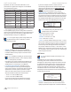
airOS™ v5.5.4 User Guide Advanced Ethernet Settings Chapter 6: Advanced Tab The following tables list the default threshold values for devices with two, three, four, or six LEDs. Two LEDs LED Default Threshold Value 1 -94 dBm 2 -65 dBm LED Default Threshold Value 1 - 94 dBm 2 -77 dBm 3 -65 dBm LED Default Threshold Value 1 -94 dBm Signal LED Thresholds 2 -80 dBm (This feature is not available on all devices.
airOS™ v5.5.4 User Guide Chapter 7: Services Tab Chapter 7: Services Tab Ping Watchdog The Services tab configures system management services: Ping Watchdog, SNMP, servers (web, SSH, Telnet), NTP, DDNS, system log, and device discovery. Ping Watchdog sets the device to continuously ping a user-defined IP address (it can be the Internet gateway, for example). If it is unable to ping under the user-defined constraints, then the device will automatically reboot.
airOS™ v5.5.4 User Guide Chapter 7: Services Tab For the purpose of equipment identification, configure the SNMP agent with contact and location information: SNMP Agent Enables the SNMP agent. Ping Watchdog Enables use of Ping Watchdog. • IP Address To Ping Specify the IP address of the target host to be monitored by Ping Watchdog. • SNMP Community Specify the SNMP community string. It is required to authenticate access to Management Information Base (MIB) objects and functions as an embedded password.
airOS™ v5.5.4 User Guide • Authorized Keys Click Edit to import a public key file for SSH access to the device instead of using an admin password. -- Choose File Click Choose File to locate the new key file. Select the file and click Open. -- Import Imports the file for SSH access. -- Enabled Enables the specific key. All the added keys are saved in the system configuration file; however, only the enabled keys are active on the device.
airOS™ v5.5.4 User Guide Chapter 7: Services Tab System Log System Log This option enables the registration routine of system log (syslog) messages. By default it is disabled. • Remote Log Enables the syslog remote sending function. System log messages are sent to a remote server, which is specified in the Remote Log IP Address and Remote Log Port fields. -- Remote Log IP Address The host IP address that receives syslog messages. Properly configure the remote host to receive syslog protocol messages.
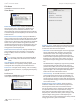
airOS™ v5.5.4 User Guide Chapter 8: System Tab The System tab contains administrative options. This page enables the administrator to reboot the device, reset it to factory defaults, upload new firmware, back up or update the configuration, and configure the administrator account. Chapter 8: System Tab Firmware Update This section manages the firmware maintenance. Change To save or test your changes, click Change. Firmware Version Displays the current firmware version. A new message appears.
airOS™ v5.5.4 User Guide This is a three-step procedure: 1. Click Choose File to locate the new firmware file. Select the file and click Open. 2. Click Upload to upload the new firmware to the device. 3. The Uploaded Firmware Version is displayed. Click Update to confirm. Chapter 8: System Tab System Accounts You can change the administrator password to protect your device from unauthorized changes.
airOS™ v5.5.4 User Guide UNII-2 Band This option is available if DFS (Dynamic Frequency Selection) frequencies in the UNII-2 band (5.25 - 5.725 GHz) should be available for your device but are locked. To unlock the DFS frequencies, follow these instructions: 1. Visit www.ubnt.com/fcclabelrequest and follow the online instructions to request the activation key and FCC labels. 2. After you have received your activation key and FCC labels, check the box next to UNII-2 Band. 3.
airOS™ v5.5.4 User Guide Chapter 9: Tools Chapter 9: Tools Noise Level Displays the noise level (in dBm) of the received wireless signal. Each tab of the airOS interface contains network administration and monitoring tools. Click the Tools drop‑down list at the top right corner of the page. Max Signal Displays the maximum signal strength (in dBm). To adjust the range of the Max Signal meter, use the slider or manually enter the new value.
airOS™ v5.5.4 User Guide Chapter 9: Tools Site Survey Network Ping The Site Survey tool searches for wireless networks in range on all supported channels. In Station mode, you can change the frequency list; for details, see “Frequency Scan List, MHz” on page 21. Select Destination IP You have two options: The Site Survey tool reports the MAC Address, SSID, Device Name, Encryption type (if any), Signal/Noise in dBm, Frequency in GHz, and the wireless Channel of each AP in the surrounding environment.
airOS™ v5.5.4 User Guide Speed Test This utility allows you to test the connection speed between two airOS devices that are using firmware version 5.2 or above. You can use Speed Test to estimate a preliminary throughput between two network devices. Note: If traffic shaping is enabled on either device, then the Speed Test results will be limited accordingly. Chapter 9: Tools Test Results Displays three result categories: • RX Displays the estimated incoming throughput.
airOS™ v5.5.4 User Guide Main View Device Displays the device name, MAC (Media Access Control) address, and IP address of the device running airView. Chapter 9: Tools Preferences Changes airView settings, such as enabling or disabling charts and traces, or specifying the frequency interval. Preferences Select View > Preferences to display the Preferences airView Spectrum Analyzer window.
airOS™ v5.5.4 User Guide • Channel Usage For each Wi-Fi channel, a bar displays a percentage showing the relative “crowdedness” of that specific channel. To calculate this percentage, the airView Spectrum Analyzer analyzes both the popularity and strength of RF energy in that channel since the start of an airView session. Enable Waveform chart (middle) Check the box to enable the middle chart. This time-based graph shows the RF signature of the noise environment since the start of the airView session.
airOS™ v5.5.4 User Guide Appendix A: Contact Information Appendix A: Contact Information Ubiquiti Networks Support Ubiquiti Support Engineers are located around the world and are dedicated to helping customers resolve software, hardware compatibility, or field issues as quickly as possible. We strive to respond to support inquiries within a 24-hour period. Online Resources Support: support.ubnt.com Wiki Page: wiki.ubnt.com Support Forum: forum.ubnt.com Downloads: downloads.ubnt.