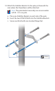
0. Attach the Stabilizer Brackets to the pole just beneath the area where the PowerBeam will be attached. Note: The pole-bracket assembly can accommodate a Ø 38 - 101 mm pole. a. Place one Stabilizer Bracket on each side of the pole. b. Insert the two M10x100 Bolts into the Stabilizer Brackets. c. Secure each bolt with one Serrated Flange Nut.
11. Attach the pole-bracket assembly to the pole: a. Slide the slot of each Pole Clamp over the corresponding M8x150 Carriage Bolt. b. Tighten the serrated flange nuts of the bolts to secure the pole-bracket assembly to the pole.
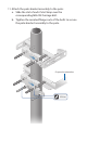
12. Lift the Dish Reflector and align the two lower Hex Head Bolts with the slots on the Lower Pole Bracket. Seat the bolts in the slots. 13. Attach each arm of the Upper Pole Bracket to the Mounting Bracket using a Hex Head Bolt, Lock Washer, and Flat Washer.
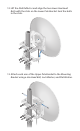
14. Before adjusting the tilt angle, ensure that the six Hex Head Bolts are loose enough to allow movement. IMPORTANT: If you cannot spin the washers freely by hand, then loosen the Hex Head Bolts until you can. 15. To adjust the tilt angle, turn the screw head of the elevation rod until the desired tilt is reached. 16. Lock the alignment by tightening all six Flange Bolts to 25 N-m.
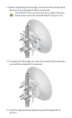
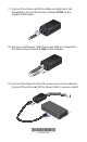
17. Connect the other end of the Ethernet cable from the PowerBeam to the Ethernet port labeled POE on the Gigabit PoE Adapter. 18. Connect an Ethernet cable from your LAN or computer to the Ethernet port labeled LAN on the adapter. 19. Connect the Power Cord to the power port on the adapter. Connect the other end of the Power Cord to a power outlet.
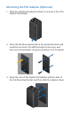
Mounting the PoE Adapter (Optional) 1. Slide the PoE Mounting Bracket down to remove it from the Gigabit PoE Adapter. 2. Place the PoE Mounting Bracket at the desired location and mark the two holes. Pre-drill the holes if necessary, and then secure the bracket using two fasteners (not included). 3. Align the slots of the Gigabit PoE Adapter with the tabs of the PoE Mounting Bracket, and then slide the adapter down.
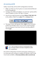
Accessing airOS Verify connectivity in the airOS Configuration Interface. 1. Make sure that your host system is connected via Ethernet to the PowerBeam. 2. Configure the Ethernet adapter on your host system with a static IP address on the 192.168.1.x subnet. 3. Launch your web browser and type https://192.168.1.20 in the address field. Press enter (PC) or return (Mac). 4. The login screen will appear. Enter ubnt in the Username and Password fields. Select your Country and Language.
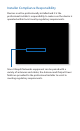
Installer Compliance Responsibility Devices must be professionally installed and it is the professional installer's responsibility to make sure the device is operated within local country regulatory requirements. Since Ubiquiti Networks equipment can be paired with a variety of antennas and cables, the Antenna and Output Power fields are provided to the professional installer to assist in meeting regulatory requirements.
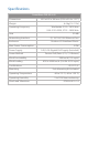
Specifications PowerBeam PBE-M5-620 Dimensions Weight Operating Frequency Gain 650 x 650 x 386 mm (25.6 x 25.6 x 15.2") 6.4 kg (14.11 lb) Worldwide: 5150 - 5875 MHz USA: 5150-5250, 5725 - 5850 MHz 29 dBi Networking Interface (1) 10/100/1000 Ethernet Port Enclosure Outdoor UV Stabilized Plastic Max. Power Consumption Power Supply Power Method Wind Survivability Wind Loading Certifications Mounting 8.5W 24V, 0.