High-Performance Integrated InnerFeed® airMAX® ac Bridge Model: PBE-5AC620
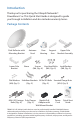
Introduction Thank you for purchasing the Ubiquiti Networks® PowerBeam® ac. This Quick Start Guide is designed to guide you through installation and also includes warranty terms. Package Contents Dish Reflector with Mounting Bracket Lower Pole Bracket Antenna Feed Brace Rear Support Upper Pole Housing Arm Bracket Assembly Screws Hex Head Bolts (M6, Qty. 4) (M8, Qty. 5) Lock Washers (M8, Qty. 5) Flat Washers Stabilizer Brackets M10x100 Bolts Serrated Flange Nuts (M8, Qty. 5) (Qty. 2) (Qty.
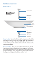
Hardware Overview Bottom View Antenna Feed Technology Ethernet Port Reset Button Release Button Dish Reflector Mounting Bracket Alignment Pins Rear Housing Release Button Slot Cable Door Reset Button To reset to factory defaults, press and hold the Reset button for more than 10 seconds while the PowerBeam is already powered on. Alternatively, the PowerBeam may be reset remotely via a Reset button located on the bottom of the Gigabit PoE Adapter.
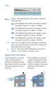
LEDs Signal The default values (from left to right) are shown below: LED will light blue when the wireless signal strength is equal to or above -65 dBm. LED will light blue when the wireless signal strength is equal to or above -73 dBm. LED will light blue when the wireless signal strength is equal to or above -80 dBm. LED will light blue when the wireless signal strength is equal to or above -94 dBm.
Installation Requirements • • • • Phillips screwdriver 13 mm wrench 16 mm wrench Shielded Category 5 (or above) cabling should be used for all wired Ethernet connections and should be grounded through the AC ground of the PoE. We recommend that you protect your networks from the most brutal environments and devastating ESD attacks with industrial‑grade shielded Ethernet cable from Ubiquiti Networks. For more details, visit www.ubnt.com/toughcable Installation 1.
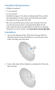
3. Attach the Antenna Feed: a. Insert the Antenna Feed into the Rear Housing, and push until it locks into place with a click. b. Lightly pull the Antenna Feed to ensure that it is locked into place and the Release button is fully engaged. Release Button Bottom View 4. Connect the Ethernet cable: a. Connect an Ethernet cable to the Ethernet Port of the Antenna Feed. b. Re-attach the Cable Door to the Rear Housing.
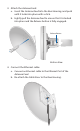
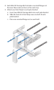
5. Attach two Hex Head Bolts, two Lock Washers, and two Flat Washers to the bottom of the Mounting Bracket. Ensure that there is a gap of 8 mm between each Flat Washer and the Mounting Bracket. Note: Ensure that each Lock Washer is always installed between the Hex Head Bolt and Flat Washer.
6. Attach the horizontal slot of the Support Arm to the Upper Pole Bracket using a Hex Head Bolt, Lock Washer, and Flat Washer. Note: Ensure that the degree settings are the same on both arms of the Upper Pole Bracket. Degree markings facing outward 7. Attach the Brace to the pole brackets using the four Screws.
8. Each M8x150 Carriage Bolt includes a serrated flange nut. Remove these and use them in the next step. 9. Attach one Pole Clamp to each pole bracket. a. Insert two M8x150 Carriage Bolts into each pole bracket. b. Slide the hole of a Pole Clamp over one bolt of each pole bracket. c. Place one serrated flange nut on each bolt.
. Attach the Stabilizer Brackets to the pole just beneath the area where the PowerBeam will be attached. Note: The pole-bracket assembly can accommodate a Ø 38 - 101 mm pole. a. Place one Stabilizer Bracket on each side of the pole. b. Insert the two M10x100 Bolts into the Stabilizer Brackets. c. Secure each bolt with one Serrated Flange Nut.
. Attach the pole-bracket assembly to the pole: a. Slide the slot of each Pole Clamp over the corresponding M8x150 Carriage Bolt. b. Tighten the serrated flange nuts of the bolts to secure the pole-bracket assembly to the pole.
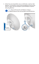
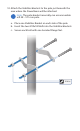
. Lift the Dish Reflector and align the two lower Hex Head Bolts with the slots on the Lower Pole Bracket. Seat the bolts in the slots. 13. Attach each arm of the Upper Pole Bracket to the Mounting Bracket using a Hex Head Bolt, Lock Washer, and Flat Washer.
14. Before adjusting the tilt angle, ensure that the six Hex Head Bolts are loose enough to allow movement. IMPORTANT: If you cannot spin the washers freely by hand, then loosen the Hex Head Bolts until you can. 15. To adjust the tilt angle, turn the screw head of the elevation rod until the desired tilt is reached. 16. Lock the alignment by tightening all six Flange Bolts to 25 N-m.
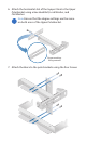
Note: Steps 17-20 are optional instructions for mounting the Gigabit PoE Adapter on a wall. 17. Remove the wall-mount bracket from the Gigabit PoE Adapter and position it at the desired location on the wall with the arrow pointing up. 18. Use a pencil to mark the two holes on the wall. 19. Attach the wall-mount bracket to the wall using the appropriate fasteners (not included). 20. Align the tabs of the Gigabit PoE Adapter with the slots of the wall-mount bracket and slide the Gigabit PoE Adapter down.