PowerStation2 LiteStation2 LiteStation5 User’s Guide © Copyright 2007 Ubiquiti Networks Inc. All rights reserved.
Contents INTRODUCTION ..................................................................................................2 QUICK SETUP GUIDE .........................................................................................3 CONFIGURATION GUIDE ...................................................................................7 Main Settings........................................................................................................................................8 Link Setup ..............
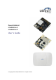
Introduction This guide presents the description of the subscriber stations LiteStation2, LiteStation5 and the outdoor wireless station PowerStation2. LiteStation2 and PowerStation2 operate in IEEE 802.11b/g modes, while the LiteStation5 operates in IEEE 802.11a mode. The devices can operate in Client (Station), Access Point and WDS modes. The screenshots in this manual are made for PowerStation2 but they are also applicable for LiteStaiton2 and LiteStaiton5.
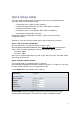
Quick Setup Guide This Quick Setup Guide will guide you through quick and easy configuration of the subscriber station (client bridge) including: Changing of the IP settings (static or dynamic), Defining the SSID to which the subscriber station will be associated, Defining the IEEE 802.11 mode, Defining the wireless security (None, WEP, WPA™ or WPA2™), Changing the administrator’s password. For detailed setup and configuration instructions, please refer to the chapter Configuration Guide.
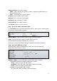
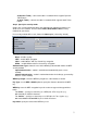
Bridge IP Address: specify the IP mode: DHCP – choose to assign the dynamic IP address, Gateway and DNS address by the local DHCP server. Static – choose to assign a static IP address. IP Address: enter IP address of the device. Netmask: enter a subnet mask of the device. Gateway IP: enter a Gateway IP address. Primary DNS IP: enter a DNS IP address. Click Change button to save the changes.
A (Dynamic Turbo) – connect to a 802.11a network which supports Dynamic Turbo feature. A (Static Turbo) – connect to a 802.11a network which supports Static Turbo feature. Step 5 Specify the security mode Choose the security method to protect your data that only authorized network users could access the network. You can choose WEP, WPA, WPA2 or None security methods for your device.
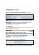
WPA Pre-shared Key: enter a passphrase for WPA™ or WPA2™ encryption. The preshared key is an alpha-numeric password between 8 and 63 characters long. Click Change button to save the changes. Step 6 Change administrator password For the security reasons the default administrator’s password should be changed immediately. Use the System menu and specify the parameters: Current Password: enter a current password value. Default administrators password is ubnt.
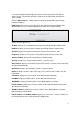
Configuration Guide Each of the web management pages (listed below) contains parameters that affect a specific aspect of the device: Figure 1 – Configuration Management Menu Main page displays current status of the device and the statistical information. Link Setup page let to prepare the device for use in a wireless network, while covering basic wireless settings – i.e. controls how a subscriber station associates to an access point, authenticates to the wireless network, encrypts and decrypts data.
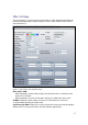
Main Settings This page displays a summary of status information. It shows important information for the device operating mode, network settings as well as traffic statistics of the wireless and LAN interfaces. Figure 2 – Current Status of the Subscriber Station Base Station SSID: While operating in Station mode, displays the SSID of the Access Point where the device has associated. While operating in in Access Point mode, displays the SSID of the device itself.
Use antenna alignment tool to adjust the device antenna to get better link with the wireless device. The antenna of wireless client has to be adjusted to get maximum signal strength. Click the Align Antenna… button and the new pop-up window with signal strength indicator will appear. RSSI Range slider can be used to change an offset of the maximum indicator value.
Extra Info: displays the current usage statistics in pop-up window: Show Stations… selection lists the stations which are connected to the device while operating in Access Point mode. Each station RSSI, Tx Rate and Idle time (sec) can be updated using the Reload button: Figure 4 – Current Status of the Associated Stations Show ARP Tables… selection lists all the entries in the system ARP tables.
Link Setup The Link Setup page allows you to manage general wireless connection parameters of the device. Basic Wireless Settings The general wireless settings, such as wireless device SSID, country code, output power, 802.11 mode and data rates can be configured on this section: Figure 8 – Basic Wireless Settings Wireless Mode: specify the operating mode of the device.
Channel: select the operating channel while operating in Access Point mode. Multiple frequency channels are available to avoid interference between nearby access points. The channel list varies depending on the selected country code and IEEE mode. Country Code: choose from drop-down list the country in which you will use the device. Output Power: specify the output power (dBm) at which wireless module transmits data using the slider.
Figure 10 – Site Survey Scan Select the Access Point from the list and click Select button for association. Click Scan button to refresh the list of available wireless networks. Close this window button closes Site Survey window. Wireless Security This section enables you to set parameters that control how the subscriber station associates to a wireless device and encrypts/decrypts data: Figure 11 – Wireless Security Settings Security: select the security mode of your wireless network.
Authentication Type: choose the one of the following authentication modes for WEP security method: Open Authentication – station is authenticated automatically. Shared Authentication – station is authenticated after the challenge, generated by AP. WEP Key Length: select the WEP Key length here, either 64-bit, or 128-bit (stronger). Key Type: use the HEX or ASCII option to specify the character format for the WEP key.
Network Settings PowerStation2/LiteStation2 and LiteStation5 can operate in bridge or router mode. The IP configuration as described below is required for device management purposes. IP addresses can either be retrieved from a DHCP server or configured manually. Use the Network menu to configure the IP settings: Figure 14 – Bridge mode Network Settings Network Mode: specify the operating network mode for the device.
Figure 15 – Router mode Network Settings There are two network segments (WLAN and LAN) configured separately when device is operating in Router mode. Wireless network segment can be configured in WLAN Network Settings section: IP Address: enter IP address of the WLAN interface. Netmask: enter a subnet mask of the WLAN interface. Enable NAT: control will enable Network Address Translation (Masquerading) feature between WLAN and LAN interfaces.
LAN IP settings can be assigned automatically using the DHCP or PPPoE. If PPPoE mode is selected, the Username and Password credentials are required for PPPoE authentication. Click Change button to save the changes. Advanced The Advanced options page allows you to manage advanced settings that influence on the device performance and behavior.
Distance: specify the distance value in miles using slider or enter the value manually. The signal strength and throughput falls off with range. Changing the distance value will change the ACK Timeout to the appropriate value of the distance. ACK Timeout: specify the ACK Timeout (20-520). This is the amount of time the subscriber station will wait to hear a acknowledgement response from the wireless device after the data packet is transmitted.
Antenna polarity defines embedded hi-gain antenna polarity: Vertical – switches vertical antenna polarity. Horizontal – switches horizontal antenna polarity. Adaptive – switches adaptive antenna polarity mode which allows for the beam polarities to be switched dynamically on the fly for improved performance in heavy noise environments.
Services This page covers the configuration of system management services SNMP and Ping Watchdog. Ping Watchdog Ping Watchdog is dedicated for continuous monitoring of the particular connection to remote host using the Ping tool. The Ping works by sending ICMP “echo request” packets to the target host and listening for ICMP “echo response” replies. If the defined number of replies is not received, the tool reboots the device.
Figure 22 – SNMP Agent Configuration Enable SNMP Agent: control will enable SNMP Agent. SNMP Community: specify SNMP community string. It is required to authenticate access to MIB objects and functions as embedded password. The device supports a Read-only community string that gives read access to authorized management stations to all the objects in the MIB except the community strings, but does not allow write access.
After the Upgrade… button is clicked the new Firmware Upload pop-up window will be displayed: Figure 24 – Firmware Upgrade. Step 2 Current Firmware: displays version of the current firmware. Firmware File: click the Browse… button to specify the new firmware image location or specify the full path and click the Upload button. Close this window – cancel the upload process. After the new firmware image is uploaded into the system, use Upgrade button to upgrade a device: Figure 25 – Firmware Upgrade.
Host Name Host Name is the system wide device identifier. It is reported by SNMP Agent to authorized management stations. Figure 27 - Host Name Configuration Host Name: specify the system identity. Click Change button to save the changes. Administrative Account In this section you can modify the administrator password to protect your device from unauthorized configuration.
To upload new logo, enable logo customization and specify the location of logo file: Figure 29 – Custom Logo Upload Enable Custom Logo: control will enable logo customization. Deselecting this option the custom logo will be removed and the default Ubiquiti logo will be restored. Logo Target URL: specify the target URL of custom logo. Target URL is opened when clicking on custom logo.
Reboot: click to hard-reboot the device in the current configuration. Any non-applied changes will be lost. Reset to Defaults: click to reset the device to factory defaults. i ii WPA™, WPA2™, Wi-Fi Protected Access™ are trademarks of the Wi-Fi Alliance. SuperG® and SuperAG® are registered trademarks of Atheros Communications, Inc.