24 GHz Point to Point 1.
Introduction Introduction Thank you for purchasing the Ubiquiti Networks® airFiber® 24 GHz Point-to-Point Radio. This Quick Start Guide is designed to guide you through installation, show you how to access the airFiber Configuration Interface, and explain how to set up an airFiber link. This Quick Start Guide also includes the warranty terms and is for use with the model AF-24. Package Contents airFiber AF-24 Carriage Bolts (M10x150, Qty. 4) Pole Mount Bracket Flat Washers (M10, Qty.
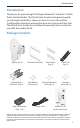
airFiber® AF-24 Quick Start Guide Hardware Overview Side Lock Bolts Alignment Bracket Elevation Adjustment Azimuth Adjustment Lock Bolts Ground Bonding Point 2
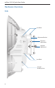
Hardware Overview Back Lock Bolts Lock Bolts Elevation Adjustment Azimuth Adjustment Lock Bolts Lock Bolts Port Cover Cover Lock 3
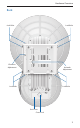
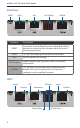
airFiber® AF-24 Quick Start Guide Interfaces RESET DATA Interface AUX LED Display CONFIG Description RESET To reset to factory defaults, press and hold the Reset button for more than five seconds while the unit is already powered on. DATA 10/100/1000 Mbps port handles all user traffic. AUX Port for audio tone aiming. LED Display Digital display used for power, status, and mode information. CONFIG 10/100 Mbps, secured port for configuration.
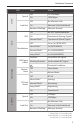
Hardware Overview LED DATA Speed Link/Act AUX GPS Modulation State Status Off 10/100 Mbps On 1000 Mbps Off No Ethernet Link On Ethernet Link Established Random Flashing Ethernet Activity Off No GPS Synchronization On Operational (Strong Signal) Normal Flash* Operational (Weak Signal) Off ¼x or 1x (QPSK SISO) Short Flash* 2x (QPSK MIMO) Normal Flash* 4x (16QAM MIMO) Long Flash* 6x (64QAM MIMO) Number RX Power Flashing Number (-dBm) Decodable RX Signal Undecodable RX Signal
airFiber® AF-24 Quick Start Guide Installation Requirements • 17 mm wrench • 13 mm socket wrench or driver • Clear line of sight between airFiber radios • Clear view of the sky for proper GPS operation • Mounting location with < 0.5° displacement due to twist and sway under wind loading • Mounting point: • At least 1 meter below the highest point on the structure • For tower installations, at least 3 meters below the top of the tower • Ground wires – min. 8 AWG (10 mm2) and max. length: 1 meter.
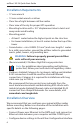
Connecting Power over Ethernet • Once configuration is complete, disconnect the cables to move the airFiber radios. • Reconnect at the site. • After you have mounted the airFiber radios, establish and optimize the RF link. Connecting Power over Ethernet 1. Turn the Cover Lock to the Unlocked down to remove it. icon. Slide the Port Cover 2. Connect an Ethernet cable to the DATA port.
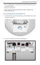
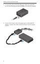
airFiber® AF-24 Quick Start Guide 3. Connect the other end of the Ethernet cable from the DATA port to the Ethernet port labeled POE on the GigE PoE Adapter. 4. Connect the Power Cord to the power port on the GigE PoE Adapter. Connect the other end of the Power Cord to a power source.
airFiber Configuration airFiber Configuration The instructions in this section explain how to access the airFiber Configuration Interface and configure the following settings: • Wireless Mode Configure one airFiber AF-24 as the Master and the other as the Slave. • Duplex The airFiber AF-24 supports both half-duplex and full‑duplex operation. Half-duplex operation provides more frequency planning options at the cost of higher latency and throughput.
airFiber® AF-24 Quick Start Guide 1. Connect an Ethernet cable from your computer to the CONFIG port on the airFiber AF-24. 2. Configure the Ethernet adapter on your computer with a static IP address on the 192.168.1.x subnet (for example, 192.168.1.100). 3. Launch your web browser. Type http://192.168.1.20 in the address field and press enter (PC) or return (Mac). 4. The login screen will appear. Enter ubnt in the Username and Password fields. Select your Country and Language.
airFiber Configuration 5. Click the Wireless tab. 6. Enter the Basic Wireless Settings: a. For one airFiber AF-24, select Master from the Wireless Mode drop-down. For the other airFiber AF-24, keep the default, Slave. b. Enter a name in the Link Name field. This should be the same on both the Master and the Slave. c. For the Duplex drop-down: -- Half Duplex The default mode. The TX and RX Frequencies can be the same or different to suit local interference.
airFiber® AF-24 Quick Start Guide 7. Configure the Wireless Security: a. Select the AES Key Type, HEX or ASCII. b. For the Key field: -- HEX Enter 16 bytes (eight, 16-bit HEX values: 0-9, A-F, or a-f ). You can omit zeroes and use colons, similar to the IPv6 format. Note: The airFiber Configuration Interface supports IPv6 formats excluding dotted quad and "::" (double‑colon) notation. -- ASCII Enter a combination of alphanumeric characters (0-9, A-Z, or a-z). 8. Click Change and then click Apply. 9.
Hardware Installation Hardware Installation To install the airFiber AF-24: 1. Insert the four Carriage Bolts into the Pole Mount Bracket. 2. Attach the Pole Mount Bracket to a pole. Note: The mounting assembly can accommodate a Ø 51 - 101 mm (2.0" - 4.0") pole. a. Orient the Pole Mount Bracket around the pole so it is aimed in the direction of the other airFiber AF-24. b. Insert the Carriage Bolts into the Pole Clamps. c. Secure the clamps with the Flat Washers, Split Lock Washers, and Hex Nuts.
airFiber® AF-24 Quick Start Guide 3. Loosen, but do NOT remove the eight Lock Bolts located on the Alignment Bracket. 4. Ensure that there is a 6 mm gap between the head of each M8x14 Serrated Flange Screw and the Alignment Bracket.
Hardware Installation 5. Lift the airFiber AF-24 and align the four M8x14 Serrated Flange Screws with the slots on the Pole Mount Bracket. Seat the screws in the slots. Securely tighten the screws. WARNING: To prevent injury, ensure that all four screws are seated and fully tightened.
airFiber® AF-24 Quick Start Guide 6. Attach a ground wire: a. Remove the nut from the Ground Bonding Point. b. Attach a ground wire (min. 8 AWG or 10 mm2) to the lug and replace the nut to secure the wire. c. Secure the other end of the ground wire to a grounded mast, pole, tower, or grounding bar. WARNING: Failure to properly ground your airFiber units will void your warranty. Note: The ground wire should be as short as possible and no longer than one meter in length.
Connecting Ethernet Connecting Ethernet 1. Turn the Cover Lock to the Unlocked down to remove it. icon. Slide the Port Cover 2. Connect a TOUGHCable or other outdoor, shielded CAT5e/6 cable to the DATA port. 3. Create a strain relief for the Ethernet cable by feeding a Cable Tie through the tie slot under the cable. Then wrap the Cable Tie around the cable and tighten.
airFiber® AF-24 Quick Start Guide 4. Connect the other end of the Ethernet cable from the DATA port to the Ethernet port labeled POE on the GigE PoE Adapter. 5. Connect an Ethernet cable from your network to the Ethernet port labeled LAN on the GigE PoE Adapter. 6. Connect the Power Cord to the power port on the GigE PoE Adapter. Connect the other end of the Power Cord to a power source. Note: For added protection, we recommend installing two GigE PoE surge protectors.
Connecting Ethernet Below is a diagram of a finished installation with recommended surge protectors installed. Ground to Pole, Tower, or Grounding Block (Max. 1 m from Ground Bonding Point) Max.
airFiber® AF-24 Quick Start Guide Alignment Tips • Fine-tuning is best achieved by a pair of installers with a dedicated, two-way communication link: one installer makes adjustments on one airFiber radio while the other installer reports the received signal level at the other airFiber radio. Fine‑tuning (see Fine-Tuning the Link) is necessary because the main lobe of the receiver is narrower than that of the transmitter, in both azimuth and elevation.
Alignment 2. For the Master and Slave, ensure the Azimuth (AZ) and Elevation (EL) Adjustment Bolts are in the middle of their adjustment ranges. Elevation (EL) Adjustment Bolt Azimuth (AZ) Adjustment Bolt 3. Master Aim the Master at the Slave. If necessary, adjust the Master's position on the pole: a. Loosen the Hex Nuts. b. Adjust the Pole Mount Bracket and Pole Clamps. c. Tighten the Hex Nuts. Hex Nuts 4.
airFiber® AF-24 Quick Start Guide 5. Master Adjust the azimuth and elevation of the Master until the strongest received signal level is displayed on the LED Display of the Master. a. Sweep the Azimuth (AZ) Adjustment Bolt of the Master through its adjustment range. Master Azimuth (AZ) Adjustment Bolt b. Sweep the Elevation (EL) Adjustment Bolt of the Master through its adjustment range.
Alignment Fine-Tuning the Link The Azimuth (AZ) and Elevation (EL) Adjustment Bolts of the Alignment Bracket adjust the azimuth and elevation within a range of ±10°. For accurate alignment, make adjustments on one end of the link while the other installer reports the received signal level at the other end of the link. Do NOT make simultaneous adjustments on the Master and Slave. 1.
airFiber® AF-24 Quick Start Guide There are three methods for determining the received signal level: • LED Display (described above) • airFiber Configuration Interface • Audio tone (optional equipment required) Refer to the airFiber AF-24 User Guide for instructions on the airFiber Configuration Interface and audio tone methods. The User Guide is available at: documentation.ubnt.
Specifications Specifications airFiber AF-24 Dimensions 649 x 426 x 303 mm (25.55 x 16.77 x 11.93") Weight 10.5 kg (23.15 lb) Mount Included Operating Frequency 24.05 – 24.25 GHz Max Power Consumption < 50W Power Supply 50V, 1.2A PoE GigE Adapter (Included) Power Method Passive Power over Ethernet (42-58VDC) Certifications CE, FCC, IC Mounting Pole Mount Kit (Included) Wind Loading 306.
airFiber® AF-24 Quick Start Guide Electrical Safety Information 1. Compliance is required with respect to voltage, frequency, and current requirements indicated on the manufacturer’s label. Connection to a different power source than those specified may result in improper operation, damage to the equipment or pose a fire hazard if the limitations are not followed. 2. There are no operator serviceable parts inside this equipment. Service should be provided only by a qualified service technician. 3.
Limited Warranty Warranty Conditions The above warranty does not apply if the Product: (I) has been modified and/or altered, or an addition made thereto, except by Ubiquiti Networks, or Ubiquiti Networks’ authorized representatives, or as approved by Ubiquiti Networks in writing; (II) has been painted, rebranded or physically modified in any way; (III) has been damaged due to errors or defects in cabling; (IV) has been subjected to misuse, abuse, negligence, abnormal physical, electromagnetic or electr
airFiber® AF-24 Quick Start Guide Disclaimer EXCEPT FOR ANY EXPRESS WARRANTIES PROVIDED HEREIN, UBIQUITI NETWORKS, ITS AFFILIATES, AND ITS AND THEIR THIRD PARTY DATA, SERVICE, SOFTWARE AND HARDWARE PROVIDERS HEREBY DISCLAIM AND MAKE NO OTHER REPRESENTATION OR WARRANTY OF ANY KIND, EXPRESS, IMPLIED OR STATUTORY, INCLUDING, BUT NOT LIMITED TO, REPRESENTATIONS, GUARANTEES, OR WARRANTIES OF MERCHANTABILITY, ACCURACY, QUALITY OF SERVICE OR RESULTS, AVAILABILITY, SATISFACTORY QUALITY, LACK OF VIRUSES, QUIET ENJO
Compliance Note Some countries, states and provinces do not allow exclusions of implied warranties or conditions, so the above exclusion may not apply to you. You may have other rights that vary from country to country, state to state, or province to province. Some countries, states and provinces do not allow the exclusion or limitation of liability for incidental or consequential damages, so the above limitation may not apply to you.
airFiber® AF-24 Quick Start Guide Industry Canada CAN ICES-3(A)/NMB-3(A) This Class A digital apparatus complies with Canadian CAN ICES-3(A). To reduce potential radio interference to other users, the antenna type and its gain should be so chosen that the equivalent isotropically radiated power (e.i.r.p.) is not more than that permitted for successful communication. This device complies with Industry Canada licence-exempt RSS standard(s). Operation is subject to the following two conditions: 1.
Declaration of Conformity CE Marking CE marking on this product represents the product is in compliance with all directives that are applicable to it. This equipment is intended to be accessed only by service personnel and/or trained professionals. Alert Sign (!) Follows CE Marking Alert sign must be indicated if a restriction on use applied to the product and it must follow the CE marking.
airFiber® AF-24 Quick Start Guide Magyar [Hungarian] Alulírott, UBIQUITI NETWORKS nyilatkozom, hogy a UBIQUITI NETWORKS device, megfelel a vonatkozó alapvetõ követelményeknek és az 1999/5/EC irányelv egyéb elõírásainak. Íslenska [Icelandic] Hér me l sir UBIQUITI NETWORKS yfir ví a UBIQUITI NETWORKS device, er í samræmi vi grunnkröfur og a rar kröfur, sem ger ar eru í tilskipun 1999/5/EC.
www.ubnt.com Support support.ubnt.com Community community.ubnt.com Downloads downloads.ubnt.com © 2012-2014 Ubiquiti Networks, Inc. All rights reserved. Ubiquiti, Ubiquiti Networks, the Ubiquiti U logo, the Ubiquiti beam logo, airFiber, EdgeRouter, and TOUGHCable are trademarks or registered trademarks of Ubiquiti Networks, Inc. in the United States and in other countries. All other trademarks are the property of their respective owners.