
User's Manual


10
Chapter 2: Installation airFiber X User Guide
Ubiquiti Networks, Inc.
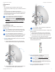
6. Repeat steps 4 and 5 until you achieve an optimal link,
with all four Signal LEDs solidly lit. This ensures the best
possible data rate between the airFiberX radios.
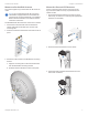
7. Lock the alignment on both airFiber antennas by
tightening all the nuts and bolts.
8. Observe the Signal LEDs of each airFiberX radio
to ensure that the values remain constant while
tightening the nuts and bolts. If any LED value changes
during the locking process, loosen the nuts and bolts,
finalize the alignment of each airFiber antenna again,
and retighten the nuts and bolts.
Refer to the following chapters of this User Guide for
details on the airFiber Configuration Interface:
• “Main Tab” on page 13
• “Wireless Tab” on page 17
• “Network Tab” on page 21
• “Advanced Tab” on page 23
• “Services Tab” on page 27
• “System Tab” on page 31
• “Tools” on page 35
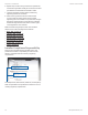
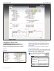
Installer Compliance Responsibility
Devices must be professionally installed and it is the
professional installer’s responsibility to make sure the
device is operated within local country regulatory
requirements.
The Output Power, Antenna Gain, Cable Loss, and Frequency
fields are provided to the professional installer to assist in
meeting regulatory requirements.