
User's Manual


3
Chapter 2: InstallationairFiber X User Guide
Ubiquiti Networks, Inc.
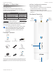
Chapter 2: Installation
Installation Requirements
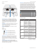
The airFiberradio operates only with the antennas listed
below:
airFiberRadio airFiberX Antenna RocketDish + Conversion Kit
AF-2X AF-2G24-S45 n/a
AF-3X AF-3G26-S45 n/a
AF-4X
AF-5G30-S45
AF-5G34-S45
RD-5G30 + AF-5G-OMT-S45
RD-5G34 + AF-5G-OMT-S45
AF-5X
AF-5G23-S45
AF-5G30-S45
AF-5G34-S45
RD-5G30 + AF-5G-OMT-S45
RD-5G34 + AF-5G-OMT-S45
See the antenna’s Quick Start Guide for antenna
installation instructions.
Other Requirements
• Clear line of sight between airFiberX radios
• Clear view of the sky for proper GPS operation
• Vertical mounting orientation
• Mounting point:
• At least 1 m below the highest point on the structure
• For tower installations, at least 3 m below the top of
thetower
• Ground wires – min. 10 AWG (5 mm
2
) and max. length:
1m. Asa safety precaution, ground the airFiberX radio
to grounded masts, poles, towers, or grounding bars.
WARNING: Failure to properly ground your
airFiberX radio will void your warranty.
• (Recommended) 2 Outdoor Gigabit PoE surge protectors
Note: For guidelines about grounding and
lightning protection, follow your local electrical
regulatory codes.
• Outdoor, shielded Category 6 (or above) cabling and
shielded RJ-45 connectors are required for all wired
Ethernet connections.
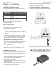
Installation Overview
We recommend to configure your paired airFiberX radios
before site installation. The overview below summarizes
the installation procedure, and the subsequent sections
provide detailed installation information:
• Connect the airFiber PoE Adapter to the DATA port, and
connect your computer and the MGMTport.
• Configure the airFiberX radio.
• Install a ground wire and mount the airFiberX radio on
an airFiberX antenna.
• At the installation site, install the airFiberX antenna with
the mounted airFiberX radio (see the antenna’s Quick
Start Guide for installation instructions).
• Secure the ground wire and mount the GPS antenna.
• Establish and optimize the RF link.
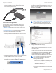
Connecting Power over Ethernet
1. Lift the release latch on the bottom of the airFiberX
radio and slide the Port Cover off.
2. Connect an Ethernet cable to the DATA port.
3. Connect the Ethernet cable from the DATA port to the
Ethernet port labeled POE on the airFiber PoE Adapter.
WARNING: Use only the included airFiber PoE
adapter, Model GP-H240-100G-4. Failure to do
so can damage the unit and void the product
warranty.