
User's Manual


2
Chapter 1: Overview airFiber X User Guide
Ubiquiti Networks, Inc.
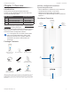
Ports
Reset
Button
Management
Port
Data
Port
Management Port 10/100 Mbps, secured Ethernet
port for configuration. In-Band Management is enabled
by default in the airFiber Configuration Interface. When
In-Band Management is disabled, the MGMT port is the
only port that can monitor, configure, and/or update
firmware.
Reset Button To reset to factory defaults, press and hold
the Reset button for more than 10 seconds while the
device is already poweredon.
Data Port Gigabit PoE port for handling all user traffic
and powering the device.
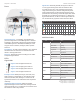
LEDs
Signal LEDs
Signal 4 LED will light blue when on.
Signal 3 LED will light green when on.
Signal 2 LED will light yellow when on.
Signal 1 LED will light red when on.
Bootup to airOS When powering on, the Power, GPS,
LINK, and Signal 1-4 LEDs light on. Once the CPU code
takes over, the GPS, LINK, and Signal 1-3 LEDs turn off.
Signal 4 LED remains on to indicate the boot sequence is
underway.
Initializing airFiber Software When the airFiber
application begins to boot under airOS, the Signal 4 LED
goes from solidly on to a 2.5 Hz flash. This continues until
the airFiberX radio is fully booted.
Signal Level Once fully booted, the Signal 1-4 LEDs act
as a bar graph showing how close the airFiberX radio
is to ideal aiming. This is auto-scaled based on the link
range, the antenna gains, and the configured TX power
of the remote airFiberX radio. Each Signal LED has three
possible states: On, Flashing, and Off. All Signal LEDs would
be solidly on in an ideal link. If the link has a 1 dB loss, the
Signal4 LED will flash; a 2 dB loss and the Signal 4 LED will
turn off. The full bar graph LED states are shown below.
dB
loss
0 -1 -2 -3 -4 -5 -6 -7 -8 -9 -10 -11 -12 -13
1 F 0 0 0 0 0 0 0 0 0 0 0 0
1 1 1 F 0 0 0 0 0 0 0 0 0 0
1 1 1 1 1 F F 0 0 0 0 0 0 0
1 1 1 1 1 1 1 1 1 1 F F F 0
0 = Off, 1 = On, F = Flashing
Additional LEDs
LED State Status
LINK
Off RF Off
Short Flash* Syncing
Normal Flash* Beaconing
Long Flash* Registering
On Operational
GPS
Off No GPS Synchronization
Normal Flash* Non-Operational (Weak Signal)
On Operational (Strong Signal)
MGMT
Off No Ethernet Link
On Ethernet Link Established
Random Flashing Ethernet Activity
DATA
Off No Ethernet Link
On Ethernet Link Established
Random Flashing Ethernet Activity
Off No Power
On Powered On
* Short Flash (1:3 on/off cycle)
Normal Flash (1:1 on/off cycle)
Long Flash (3:1 on/off cycle)