2.
airFiber X User Guide Table of Contents Table of Contents Chapter 1: Overview. . . . . . . . . . . . . . . . . . . . . . . . . . . . . . . . . . . . . . . . . . . . . . . . 1 Introduction. . . . . . . . . . . . . . . . . . . . . . . . . . . . . . . . . . . . . . . . . . . . . . . . . . . . . . . . . . . . . . . . . . . . . . 1 Package Contents. . . . . . . . . . . . . . . . . . . . . . . . . . . . . . . . . . . . . . .
Table of Contents airFiber X User Guide Chapter 8: Services Tab. . . . . . . . . . . . . . . . . . . . . . . . . . . . . . . . . . . . . . . . . . . . 27 Ping Watchdog. . . . . . . . . . . . . . . . . . . . . . . . . . . . . . . . . . . . . . . . . . . . . . . . . . . . . . . . . . . . . . . . . . 27 SNMP Agent. . . . . . . . . . . . . . . . . . . . . . . . . . . . . . . . . . . . . . . . . . . .
airFiber X User Guide Table of Contents Appendix D: Safety Notices. . . . . . . . . . . . . . . . . . . . . . . . . . . . . . . . . . . . . . . . 53 Electrical Safety Information. . . . . . . . . . . . . . . . . . . . . . . . . . . . . . . . . . . . . . . . . . . . . . . . . . . . . 53 Appendix E: Warranty. . . . . . . . . . . . . . . . . . . . . . . . . . . . . . . . . . . . .
Table of Contents iv airFiber X User Guide Ubiquiti Networks, Inc.
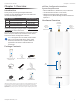
airFiber X User Guide Chapter 1: Overview Chapter 1: Overview airFiber Configuration Interface System Requirements Introduction • Microsoft Windows 7, Windows 8; Linux; or Mac OS X Thank you for purchasing the Ubiquiti Networks® airFiber® X Carrier Backhaul Radio. This User Guide is for use with the following models: • Java Runtime Environment 1.6 (or above) Model Description AF-2X 2.
Chapter 1: Overview airFiber X User Guide Ports Signal Level Once fully booted, the Signal 1-4 LEDs act as a bar graph showing how close the airFiber X radio is to ideal aiming. This is auto-scaled based on the link range, the antenna gains, and the configured TX power of the remote airFiber X radio. Each Signal LED has three possible states: On, Flashing, and Off. All Signal LEDs would be solidly on in an ideal link.
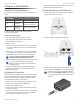
airFiber X User Guide Chapter 2: Installation Chapter 2: Installation • Secure the ground wire and mount the GPS antenna. Installation Requirements Connecting Power over Ethernet The airFiber radio operates only with the antennas listed below: 1. Lift the release latch on the bottom of the airFiber X radio and slide the Port Cover off. airFiber Radio airFiber X Antenna • Establish and optimize the RF link.
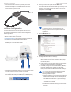
Chapter 2: Installation 4. Connect the Power Cord to the power port on the airFiber PoE Adapter. Connect the other end of the Power Cord to a power source. airFiber Configuration The instructions in this section explain how to access the airFiber Configuration Interface and configure the following settings: airFiber X User Guide 4. The login screen will appear. Enter ubnt in the Username and Password fields. Select your Country and Language. You must agree to the Terms of Use to use the product.
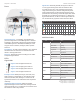
airFiber X User Guide 7. Configure the Frequency Settings. The selected Frequency must be the same on both airFiber X radios. 8. Configure the Wireless Security: a. Select the AES Key Type, HEX or ASCII. b. For the Key field: -- HEX Enter 16 bytes (eight, 16-bit HEX values: 0-9, A-F, or a-f ). You can omit zeroes and use colons, similar to the IPv6 format. Note: The airFiber Configuration Interface supports IPv6 formats excluding dotted quad and “::” (double‑colon) notation.
Chapter 2: Installation Mount to an Antenna The airFiber X radio can be mounted to the antenna(s) listed in “Installation Requirements” on page 3. The airFiber X Antenna (AF-5G30-S45) is shown in the following steps: airFiber X User Guide 3. Attach the External GPS Antenna (included with the radio) to the RF connector labeled GPS on the radio. 1. Attach the airFiber X radio to the antenna by aligning the four tabs on the back of the radio with the slots of the radio mount.