
Programming instructions

Intermec Fingerprint v7.61 – Programmer’s Reference Manual Ed. 7 285
Chapter 3 Image Transfer
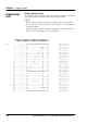
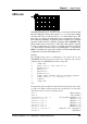
The image illustrated above contains 2 bytes (= 16 bits) in each horizontal
line. By setting the absolute start position to x = 8, you can start counting
from the start of the second byte, that is x = 8 in the matrix above. The
fi rst 3 bits (x-positions) are white, then comes one black bit followed by
three white bits, and fi nally one black bit. Expressed in 0:s and 1:s, where 0
represents a white bit and 1 a black bit, the pattern will be 00010001. This
binary number can be expressed as 11 hex. The same pattern is repeated
for each y-position from y = 1 thru y = 7 with the exception of position y
= 4, where all bits are black except for the leading three, i.e. the pattern is
00011111, which can be expressed as 1F hex. Use this hexadecimal values
as input data as shown in the example below.
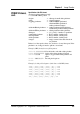
Example:
The simplifi ed image above is transmitted to the printer. Do not use
XON/XOFF (11 hex/13 hex) protocol, since these characters may coincide
with input data. Use RTS/CTS instead. Do not strip LF.
10 STORE OFF
20 OPEN ”uart1:” FOR INPUT AS #1
30 QNAME$=”H.1”
40 QWIDTH%=16
50 QHEIGHT%=10
60 QPRO$=”UBI10”
70 STORE IMAGE QNAME$,QWIDTH%,QHEIGHT%,QPROT$
80 STORE INPUT 900,4: ’Timeout 9 sec.
90 CLOSE#1
100 STORE OFF
RUN
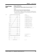
The input string in line 80 should contain the following data. Carriage returns
(↵ ) after each !SB set of data increments the y-position by 1 in consecutive
order. It may also be sent as a continuous string.
!BG ↵ (Begin graphic)
!X8A ↵ (Set x-position)
!Y1A!SB1W<11 hex> ↵ (Set y-position + data for y = 1)
!SB1W<11 hex> ↵ (Data for y = 2)
!SB1W<11 hex> ↵ (Data for y = 3)
!SB1W<1F hex> ↵ (Data for y = 4)
!SB1W<11 hex> ↵ (Data for y = 5)
!SB1W<11 hex> ↵ (Data for y = 6)
!SB1W<11 hex>!EG ↵ (Data for y = 7 + end graphics)
!PRINT ↵ (End frame)
UBI10, cont.