
User Manual
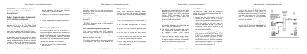
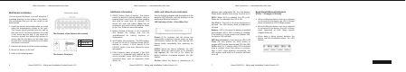
Table Of Contents

540.00874.005
Ubee Interactive — www.ubeeinteractive.com
5 Ubee DVW3231 – Safety and Installation Product Insert v2.0
Wall-Mount Installation
You can mount the device on a wall using the 2
mounting brackets on the bottom of the device.
We recommend that you use two round or pan
head screws.
1. Install two screws horizontally apart on a wall
using the measurement shown to the right.
The screws should protrude from the wall so
that you can fit the device between the head
of the screw and the wall. If you install the
screws in drywall, use hollow wall anchors to
ensure that the unit does not pull away from
the wall due to prolonged strain from the cable
and power connectors.
2. Remove the device from the product package.
3. Mount the device on the wall.
4. Refer to the following figure.
The Distance of the Pothook (Horizontal)
The Screw’s Size (mm)
163mm
(
6.4 inches
)
A
B C
A 6.65+/-0.35
B 1.9+/-0.15
C 19.0+/1.20
Ubee Interactive — www.ubeeinteractive.com
6 Ubee DVW3231 – Safety and Installation Product Insert v2.0
Additional Information
1. RESET Button (back of device): This button
resets the device to factory defaults. Using a
pointed object, insert it into the button opening,
and hold for more than 10 seconds. The
device will reset and reboot. Note: Not all
parameters are reset to factory defaults. Refer
to the User Guide for more information.
2. Battery (bottom of device): A slot is provided
that houses the battery and can be
opened/closed for battery insertion or
replacement.
3. WPS button (top of device): The WPS button
is used for the Wi-Fi Protected Setup (WPS)
method to connect a Wi-Fi device to the
DEVICE. Refer to the User Manual for more
information.
4. USB Connector (back of device): If the USB
connector is supported and enabled by the
service provider, some USB devices can be
connected here, such as computers, flash
drives, etc.
LEDs and Other Device Indicators
See the following diagram and descriptions of the
device’s LED behavior, and the behavior of the
back-panel Ethernet indicators.
LED Indicators (Color = Blue When On):
Power—If On, indicates that the device has
successfully completed internal power-on tests.
LED flashes if power-on fails. Note that the LED
flashes briefly immediately after powering the
device.
US/DS—When the device initializes, the LED
flashes. When the device locks on to channels
and registers OK, the LED is On. When the
device performs a firmware upgrade, the LED
flashes.
On-line—When the device is obtaining an IP
Ubee Interactive — www.ubeeinteractive.com
7 Ubee DVW3231 – Safety and Installation Product Insert v2.0
address and configuration file, the LED flashes.
When device obtains these items, the LED is On.
Wi-Fi—When Wi-Fi is enabled, the LED is On.
When Wi-Fi is disabled, the LED is Off.
Tel 1/Tel 2—The LED is On when a telephone is
on-hook. The LED flashes when a telephone is
off-hook.
Battery—LED is On when the battery is installed
and charged. LED is Off if no battery is installed.
If the battery is at low power level (30mins left),
the battery LED will flash.
WPS (top of device)—If not used, the LED is Off.
When the user pushes the WPS button or
triggers WPS via the device’s web GUI, the LED
flashes white for 4 minutes until a PIN is entered
from a wireless client that wishes to connect.
After a Wi-Fi client attaches successfully, the
LED remains solid white for 5 minutes, and then
turns off.
Back Panel Ethernet Indicators
(Color = Orange or Green):
x When an Ethernet device, such as a computer,
is connected to the device, the LED is Orange
when connected at 10/100 Mbps speeds.
x When an Ethernet device, such as a computer,
is connected to the device, the LED is Green
when connected at 1000 Mbps speeds
(Gigabit Ethernet).
x When data is being passed between the
device and the connected device, the LED
flashes.