
User's Manual


LED COLOR DESCRIPTION
POWER Green
On–Device has successfull
y
completed internal
power on tests. BLINKS i
f
ϋ
power on self test failsϋ
SYNCH Green Indicates the connection
status between the device
and the cable network.
The LED is lit when the
device has established a DS
channel with MSO’s CMTS
(Cable Modem Termination
Equipment)
The LED will flash during
registration process network
Blinks quickly–Acquiring IP
address and configuration
file.
Off–Device receives disable
configuration file message.
WLAN Green On–At least one wireless
client is linked to the device.
Blinks–Indicates modem
traffic.
Off–No wireless clients
connected.
WPS Green On–WPS used.
Off–WPS not used.
ETHERNET
1,2,3,4
Green
or
Orange
On–Connectivity between
Ethernet ports on the device
and computer:
- Green – 100Mbps
- Orange – 10Mbps
Blinks–Sending or receiving
data.
Note: Sync and Ready LEDs blink during a firmware
upgrade.
Figure 3: Front Panel LEDs
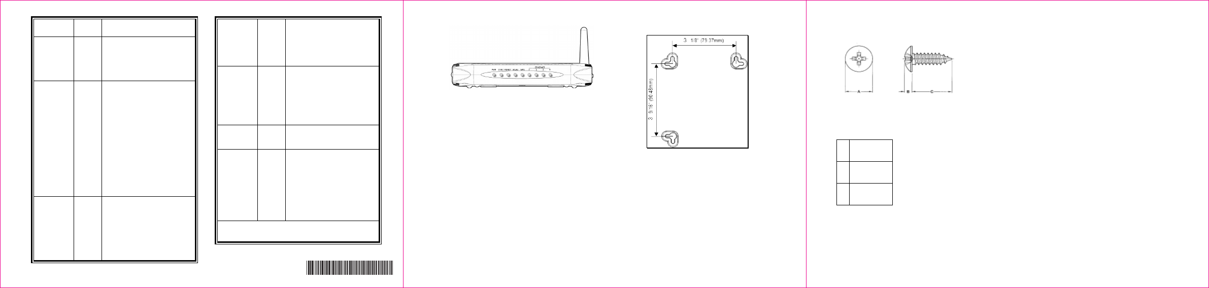
i Wall Mount Installation
You can mount the device on a wall using the
mounting brackets on the bottom of the device.
Refer to Figure 4. It is recommended to use two
round or pan head screws, not included, as
shown in Figures 5 and 6.
1. Install two screws horizontally apart on a wall
using the measurements shown in Figure 4.
Ensure the screws protrude from the wall to fit the
device between the head of the screw and the
wall. If the screws are installed in drywall, use
hollow wall anchors to ensure the unit does not
pull away from the wall due to prolonged strain
from the cable and power connectors.
Figure 4: Mounting bracket measurements
2. Remove the device from the product package.
3. Mount the device on the wall.
Ready Green On–Ranging registration
process is successful and the
device is ready to send and
receive data.
Blinks slowly–Performing
upstream ranging.
Figure 5: Bracket distances
A 6.65+/-0.35
B 1.9+/-0.15
C 19.0+/ 1.20
Figure 6: Screw sizes
4
5
6
540. 00776. 005
-