Warranty Statement 30 GALLON 12.75 HP KOHLER GAS ENGINE AIR COMPRESSOR LIMITED WARRANTY Harbor Freight Tools Co. makes every effort to assure that its products meet high quality and durability standards, and warrants to the original purchaser that this product is free from defects in materials and workmanship for a period of two years from date of purchase. (90 days if used by a professional contractor or if used as rental equipment).
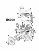
Safety Instructions Pump B6000 S2AK74H BA69 IC34 5001369 Safety Valve (200 psi) SV25200 Discharge Tube DT027 Unloader/Pilot Valve U109 Pressure Gauge GA300 September 2005 Tank TK30GB Drive Pulley Belt(2) Idle Control Beltguard Filter Assem. Beltguard Fastener BG31184R FS002 Parts List US1230G Ball Valve BV75 Tank Drain FIB02DC16 Engine ECS12ST Warning indicates a potentially hazardous situation which, if not avoided, COULD result in death or serious injury.
Safety Instructions (continued) 10. Keep fingers away from a running compressor; fast moving and hot parts will cause injury and/or burns. a flammable gas or vapor. Never store flammable liquids or gases in the vicinity of the compressor. 11. If the equipment should start to vibrate abnormally, STOP the engine/motor and check immediately for the cause. Vibration is generally a warning of trouble. ! WARNING NEVER refuel a running or hot engine. Explosive fuel can cause fires and severe burns.
B6000 16. Fast moving air will stir up dust and debris which may be harmful. Release air slowly when draining moisture or depressurizing the compressor system. 17. STOP the engine whenever leaving the work area, before cleaning, making repairs or inspections. When cleaning, 35 36 3 37 43 22 40 19. Do not smoke when spraying paint, insecticides, or other flammable substances.
Glossary of Terms Troubleshooting ASME Safety Valve A safety valve that automatically releases the air if the air receiver (tank) pressure exceeds the preset maximum. Regulator (Not Included) A control that adjusts the line pressure to the proper amount needed to operate spray guns and air tools. PSI (Pounds per Square Inch) Measurement of the pressure exerted by the force of the air. The actual psi output is measured by a pressure gauge on the compressor.
Troubleshooting Getting to Know Your Air Compressor Air Filter ! WARNING For your own safety do not try and run the air compressor while troubleshooting. Belt Guard TROUBLE Low discharge pressure PROBABLE CAUSE REMEDY 1. Listen for escaping air. Ally soap solution to all fittings and connections. Bubbles will appear at points of leakage. Tighten or replace leaking fittings or connections 1. Air leaks 2. Remove head and inspect for valve breakage, weak valves, scored valve plate, etc.
Operating Your Compressor (continued) Operating Your Compressor NOTICE ! Before starting the compressor, thoroughly read all component instruction manuals, especially the engine manual. All lubricated compressor pumps discharge some condensed water and oil with the compressed air. Install appropriate water/oil removal equipment and controls as necessary for the intended application. CAUTION Do not attach air tools to open end of the hose until start-up is completed and unit checks OK.
Table of Contents Section Notes Page Section Safety Instructions Safety Signal Words Before Using the Air Compressor Spraying Precautions Breathable Air Warning 1 1 1 3 3 Maintenance Maintenance Schedule Adjusting the Regulator Filter Removal, Inspection, and Replacement Drive Belt Glossary of Terms 4 Troubleshooting Unpacking and Checking Content 4 Replacement Parts Getting to Know Your Air Compressor 5 Operating Your Air Compressor Moisture in Compressed Air Lubricaton Start-up To Start Gaso
35 36 3 37 42 43 25 22 40 B6000 7 19 16 41 20 17 34 21 2 18 11 46 13 12 23 14 30 9 15 29 45 27 8 1 4 26 31 47 38 24 6 28 44 32 33 10 39 5
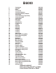
B6000 1. 2. 3. 4. 5. 6. 7. 8. 9. 10. 11. 12. 13. 14. 15. 16. 17. 18. 19. 20. 21. 22. 23. 24. 25. 26. 27. 28. 29. 30. 31. 32. 33 34. 35. 36. 37. 38. 39. 40. 41. 42. 43. 44. 45. 46. 47.
OWNER'S MANUAL COMMAND PRO CS SERIES 4-12 HP HORIZONTAL CRANKSHAFT
Safety Precautions To insure safe operations please read the following statements and understand their meaning. Also refer to your equipment owner's manual for other important safety information. This manual contains safety precautions which are explained below. Please read carefully. WARNING Warning is used to indicate the presence of a hazard that can cause severe personal injury, death, or substantial property damage if the warning is ignored.
Safety Precautions (Cont.) WARNING WARNING WARNING Accidental Starts can cause severe injury or death. Carbon Monoxide can cause severe nausea, fainting or death. Explosive Gas can cause fires and severe acid burns. Disconnect and ground spark plug lead before servicing. Do not operate engine in closed or confined area. Charge battery only in a well ventilated area. Keep sources of ignition away. Accidental Starts! Disabling engine. Accidental starting can cause severe injury or death.
Air Cleaner Cover Retaining Knob Air Cleaner Fuel Tank Cap Muffler Shield Fuel Tank On/Off Switch (some models) Muffler Oil Sentry Light Spark Plug Fuel Shut-Off Valve Cover Choke Lever Retractable Starter Throttle Lever Oil Fill/ Check Plug Oil Drain Carburetor Figure 1. Location of Controls and Service Points on CS Engines. Oil Recommendations Using the proper type and weight of oil in the crankcase is extremely important. So is checking oil daily and changing oil regularly.
Fuel Recommendations Engine Identification Numbers WARNING: Explosive Fuel! Gasoline is extremely flammable and its vapors can explode if ignited. Store gasoline only in approved containers, in well ventilated, unoccupied buildings, away from sparks or flames. Do not fill the fuel tank while the engine is hot or running, since spilled fuel could ignite if it comes in contact with hot parts or sparks from ignition. Do not start the engine near spilled fuel. Never use gasoline as a cleaning agent.
Operating Instructions Also read the operating instructions of the equipment this engine powers. Pre-Start Checklist NOTE: This engine has been shipped without engine oil. Fill with oil, otherwise it will not start. Starting 1. Turn fuel shut-off valve to on position. See Figure 6. Check oil level. Add oil if low. Do not overfill. Check fuel level. Add fuel if low. Check cooling air intake areas and external surfaces of engine. Make sure they are clean and unobstructed.
WARNING: Accidental Starts! Disabling engine. Accidental starting can cause severe injury or death. Before working on the engine or equipment, disable the engine as follows: 1) Disconnect the spark plug lead(s). 2) Disconnect negative (-) battery cable from battery. For an Electric Start Engine Activate the starter switch. Release the switch as soon as the engine starts. On Off Stopping 1. If possible, remove the load. 2. Move the throttle control to the slow or low idle position.
Maintenance Instructions Maintenance, repair, or replacement of the emission control devices and systems, which are being done at the customers expense, may be performed by any non-road engine repair establishment or individual. Warranty repairs must be performed by an authorized Kohler service outlet. WARNING: Accidental Starts! Disabling engine. Accidental starting can cause severe injury or death.
NOTE: Just because you can see oil in the crankcase doesn't mean the level is in the safe range. Bring the level up to the point of overflowing the filler neck. Filler Neck Bring Level Up To Point of Overflow (Cutaway Showing Proper Oil Level) Figure 10. Proper Oil Level. 5. If the level is low, add oil of the proper type, up to the point of overflowing the filler neck. (Refer to Oil Type on page 4.) Always check the level before adding more oil.
Reduction Systems 2:1 Reduction Systems All 2:1 reduction systems are lubricated by the crankcase oil of the engine through special openings in the closure plate. No special maintenance or service is necessary. Check and maintain the oil level as outlined on pages 8 and 9. 6:1 Reduction Systems CS4 and CS6: Use an internal pinion and ring gear system, independent of, and separated from the main crankcase lubrication. See Figure 12.
On Heavy Duty Air Cleaner Systems: Remove and clean the lower dirt/swirl chamber. Make sure the openings near the base of chamber and in the air cleaner cover/housing, are not blocked or restricted. See Figure 13. 4. Position the paper element on base and secure with wing nut, then install the precleaner over the element. If element is not secured with a wing nut, place the precleaner over the element and install it as an assembly into the cover/housing.
Check Spark Plug Annually or every 100 hours of operation, remove the spark plug, check condition, and reset the gap or replace with new plug as necessary. The original plug is an NGK BPR4ES. The Champion® equivalent of that NGK plug is RN14YC. The service replacement is Champion® RC14YC (Kohler part No. 66 132 01-S). Equivalent alternate brand plugs can also be used. 1. Before removing the spark plug, clean the area around the base of the plug to keep dirt and debris out of the engine. 2.
Muffler Screen and Spark Arrestor Engines are equipped with a muffler screen and spark arrestor for operational and environmental safety. One of two configurations will be used, determined by the engine model involved. Every 100 hours of operation, remove and clean or replace the muffler screen and/or spark arrestor following the instructions below. Muffler Screen CS4,CS6 CAUTION! The engine and muffler will be very hot after the engine has been run.
Muffler Screen and Spark Arrestor CS8.5,CS10,CS12 CAUTION! The engine and muffler will be very hot after the engine has been run. Avoid touching the engine and muffler while they are still hot, with any part of your body or clothing. 1. Remove the muffler screen. 2. Remove the spark arrestor using a flatblade screwdriver. 3. Clean the carbon deposits out of the muffler screen and spark arrestor using a wire brush.
Make sure fuel is reaching the carburetor. This includes checking the fuel lines and components for restrictions or problems. Replace as necessary. 2. Low Idle Fuel Needle Setting: Place the throttle into the idle or slow position. Turn the low idle fuel adjusting needle/cap in or out within adjustment range, to obtain the best low speed performance. Make sure On-Off switch is functioning properly.
Storage If the engine will be out of service for two months or more, use the following storage procedure: 1. Clean the exterior surfaces of the engine. 2. Change the oil while the engine is still warm from operation. See Change Oil on page 9. 3. The fuel system must be completely emptied, or the gasoline must be treated with a stabilizer to prevent deterioration. If you choose to use a stabilizer, follow the manufacturers recommendations, and add the correct amount for the capacity of the fuel system.
Specifications Model: .......................................................................... CS4 Spec. Number .......................................................... 90xxxx Bore: .................................................. mm(in.) ..... 56(2.20) Stroke: ................................................ mm(in.) ..... 50(1.97) Displacement: ................................... cm3(in.3) ... 123(7.51) *Power (@ 3600 RPM): .................... kW(HP) ...... 2.98(4*) Max. Torque (@ 2400 RPM): ......
KOHLER CO. FEDERAL AND CALIFORNIA EMISSION CONTROL SYSTEMS LIMITED WARRANTY SMALL OFF-ROAD ENGINES The U.S. Environmental Protection Agency (EPA), the California Air Resources Board (CARB), and Kohler Co. are pleased to explain the Federal and California Emission Control Systems Warranty on your small off-road equipment engine. For California, engines produced in 1995 and later must be designed, built and equipped to meet the states stringent anti-smog standards.
LIMITATIONS This Emission Control Systems Warranty shall not cover any of the following: (a) repair or replacement required because of misuse or neglect, improper maintenance, repairs improperly performed or replacements not conforming to Kohler Co. specifications that adversely affect performance and/or durability and alterations or modifications not recommended or approved in writing by Kohler Co.
FOR SALES AND SERVICE INFORMATION IN U.S. AND CANADA, CALL 1-800-544-2444 FORM NO.: TP-2494 ISSUED: 8/98 REVISED: 8/01 MAILED: ENGINE DIVISION, KOHLER CO.