
Specifications


40
sehsalFsmhoniecnatsiseRlleCdaC
1004nahtsseL
2008nahtsseldna004nahteroM
30061nahtsseldna008nahteroM
40005nahtsseldna0061nahteroM
TABLE 7: CAD CELL RESISTANCE WHEN
SENSING FLAME
b. CHECK OIL PRIMARY CONTROL
NOITUAC
enilfodrazahlaitnetopehtoteuD
decneirepxe,deniartaylno,egatlov
ehtmrofrepdluohsnaicinhcetecivres
.skcehc
ytefasgniwollof
elbaecivres-dleifonsniatnoclortnocsihT
.trapatiekatottpmettatonoD.strap
tonsinoitarepofilortnoceritneecalpeR
.debircsedsa
i. Preliminary Steps
• Check wiring connections and power
supply.
• Make sure power is on to the controls.
• Make sure limit control is closed.
• Check contacts between ignitor and the
electrodes.
• Check the oil pump pressure.
• Check the piping to the oil tank.
• Check the oil nozzle, oil supply and oil
fi lter.
ii. Check Safety Features
Safe Start:
• Place a jumper across cad cell terminals.
• Follow procedure to turn on burner.
Burner must not start, indicator light turns
on and control remains in Idle Mode.
• Remove jumper.
iii. Simulate Ignition or Flame Failure:
• Follow procedure to turn on burner.
• Close hand valve in oil supply line.
• Failure occurs, device enters Recycle
Mode. Indicator light fl ashes at ¼ Hz rate
2 seconds on, 2 seconds off).
• Device tries to restart system after
approximately 60 seconds.
• After third Recycle Mode trial, safety
switch locks out within safety switch
timing indicated on label and control
enters Restricted Mode. Indicator light
fl ashes at 1 Hz rate (½ second on, ½
second off). Ignition and motor stop and
oil valves closes.
• To reset from Restricted Mode: Press and
hold the reset button for 30 seconds.
When the LED fl ashes twice, the device
has reset.
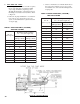
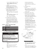
iv. Cad Cell Check: See Figure 29.
Figure 29: Cad Cell Location
• To reset from Restricted Mode: Press and
hold the reset button for 30 seconds.
When the LED fl ashes twice, the device
has reset.
v. T-T Jumper: Select models have pre-
installed T-T jumper resistor. To remove
jumper, if applicable, use side-cutting pliers
to cut jumper (See Figure 28).
vi. Diagnostic LED: The indicator light on oil
primary control provides lockout, recycle
and cad cell indications as follows:
• Flashing at 1 Hz (½ second on, ½ second
off): system is locked out or in Restricted
Mode.
• Flashing at ¼ Hz (2 seconds on, 2 seconds
off): control is in Recycle Mode.
• On: cad cell is sensing fl ame.
• Off: cad cell is not sensing fl ame.
vii. Cad Cell Resistance Check: For proper
operation it is important that the cad cell
resistance is below 1600 ohms. During a
normal call for heat, once the control has
entered the Run Mode, press and release the
reset button. Indicator light will fl ash 1 to 4
fl ashes. See Table 7 for equivalent cad cell
resistance.
• Perform cad cell resistance check as
outlined in control feature. If resistance is
below 1600 OHMS and burner runs
beyond safety cut-out time, cad cell is
good.
• If safety switch shuts down burner and
resistance is above 1600 OHMS, open line
switch to boiler. Access cad cell under