
Specifications


39
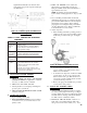
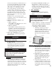
Figure 28: R7184 Terminals, LED and Reset Button
smoke tester and adjust air for minimum smoke (not
to exceed #1) with a minimum of excess air. Make
fi nal check using suitable instrumentation to obtain
a CO
2
of 11.5 to 12.5% with draft of zero inches
water column ("w.c.) (water gauge) in canopy.
These settings will assure a safe and effi cient
operating condition. If the fl ame appears stringy
instead of a solid fi re, try another nozzle of the same
type. Flame should be solid and compact. After
all adjustments are made recheck for a draft of zero
inches water column ("w.c.) in the canopy. Replace
plug at completion.
See Table 8 (at rear of this manual) for details
regarding the overfi re pressure when baffl es are both
installed and removed.
3. READJUST THE HEAD SETTING only if
necessary.
a. MPO84 & MPO147:
Beckett MB(L1 & L2) Head burners have a fi xed
head which are non-adjustable.
b. MPO189 & MPO231:
Beckett MD(V1) (variable) Head burners have
the ability to control air by moving the head. It
might be necessary to move the head forward
or back one position at a time to optimize the
smoke and CO
2
readings. See Figure 27.
4. TURN “OFF” BURNER and remove pressure
gauge. Install gauge port/bleeder plug and tighten.
Start burner again.
GNINRAW
sgnittifenillioynaevomerronesooltonoD
.gnitareposirenrubelihw
5. FLAME FAILURE
The MPO boiler controls operate the burner
automatically. If for unknown reasons the burner
ceases to fi re and the reset button on the primary
control has tripped, the burner has experienced
ignition failure.
GNINRAW
nehwrenrubehttratsottpmettatonoD
tinuehtnehw,detalumuccasahliossecxe
noitsubmocehtnehwro,ropavfollufsi
.tohyrevsirebmahc
H. CHECK FOR CLEAN CUT OFF OF
BURNER.
1. AIR IN THE OIL LINE between fuel unit and
nozzle will compress when burner is on and will
expand when burner stops, causing oil to squirt from
nozzle at low pressure as the burner slows down and
causing nozzle to drip after burner stops. Usually,
cycling the burner operation about 5 to 10 times will
eliminate air from the oil line.
2. IF NOZZLE CONTINUES TO DRIP, repeat
Paragraph H, No. 1. If this does not stop the
dripping, remove cut-off valve and seat, and wipe
both with a clean cloth until clean, then replace
and readjust oil pressure. If dripping or after burn
persist replace fuel pump.
I. TEST CONTROLS.
1. Check thermostat operation. Raise and lower
thermostat setting as required to start and stop
burner.
GNINRAW
deredisnocsireliobehtfonoitallatsnierofeB
slortnocreliobllafonoitarepoeht,etelpmoc
yramirpehtylralucitrap,dekcehcebtsum
.lortnoctimilhgihdnalortnoc
2. VERIFY PRIMARY CONTROL FEATURES
using procedures outlined in Instructions furnished
with control or instructions as follows:
a. FEATURES AND CONTROLS
i. The R7184 is a microprocessor-based
control. The indicator light provides
diagnostic information for lockout, recycling
and patented cad cell status. There is a
manual reset button to exit the Lockout
Mode and enter the Idle Mode (see Figure
28).
ii. Pump Priming Cycle: To facilitate purging
air from the oil lines and fi lters, the R7184
can be placed in a purge routine by pressing
and releasing the reset button during the
safety check, delayed valve-on, ignition or
carry-over periods.
iii. Limited Recycle: This feature limits the
number of recycle trials (for each call
for heat) to a maximum of three trials. If
the fl ame is lost three times and does not
successfully satisfy a call for heat, the
R7184 locks out.
iv. Limited Reset (Restricted Mode): In order
to limit the accumulation of unburned oil in
the combustion area, the control can only be
reset three times. The reset count returns to
zero each time a call for heat is successfully
completed.