
Specifications
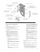


19
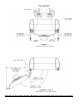
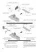
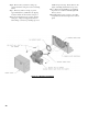
Step a. Install stainless steel baffl es provided in
miscellaneous parts carton as follows, refer to
Table 2 and Figure 11:
• Model MPO84 - To install fl ueway baffl e
in 3
rd
pass on left side of boiler, hold baffl e
with word "Left" readable at the top. Slide
baffl e in fl ueway until position tab touches
fi ns on left side of 3
rd
pass fl ueway. To
install fl ueway baffl e in 3
rd
pass fl ueway on
right side of boiler, hold baffl e with word
"Right" readable at the top. Slide baffl e in
fl ueway until position tab touches fi ns on
right side of 3
rd
pass fl ueway.
• Models MPO147, MPO189 and MPO231
- To install fl ueway baffl e in 2
nd
pass fl ueway
on left side of boiler, hold baffl e with word
"Left" readable at the top. Slide baffl e in
fl ueway until position tab touches fi ns on
right side of 2
nd
pass fl ueway. To install
fl ueway baffl e in 2
nd
pass fl ueway on right
side of boier, hold baffl e with word "Right"
readable at the top. Slide baffl e in fl ueway
until position tab touches fi ns on left side of
2
nd
pass fl ueway.
NOTE: 2nd and 3rd pass fl ueway baffl e are not
interchangable.
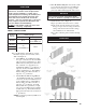
relioB
ledoM
egasUelffaB
2
dn
ssaP3
dr
ssaP
48OPMenoN
)2(
10-180001N/P
741OPM
)2(
10-240001N/P
enoN
981OPM
132OPM
TABLE 2: BAFFLE USAGE
NOITUAC
rehgihetareneglliwselffabesehT
.serutarepmetkcatsrewoldnaseicneiciffe
ssorgrewola,snoitidnocniatrecrednU
sahyenmihcehtgniretneerutarepmetkcats
wedehtwolebdeloocebotlaitnetopeht
roiretninoetasnednocetaercdnatniop
,evisorrocsietasnednocsageulF.secafrus
dnanoitaredisnoclaicepsseriuqerhcihw
.yletaidemmidesserddaeb
tsum
TONOD daerevahuoylitnuselffabllatsni
.yletelpmoc"gnitneV",VnoitceS
Figure 11: Baffl e Orientation in Flueways
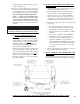
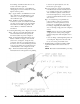
8. Close the burner swing door and securely seal the
door to the boiler front section by reinstalling the
hardware and securing the door using procedure
previously outlined in Paragraph D of this section.
ECITON
ekamroodgniwsrenrubgnirucesnehW
.sedishtobnoyllauqeni-nwardsirooderus
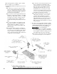
9. Install oil burner, refer to Figure 12.
Step a. Open burner carton and remove contents.
Step b. Check oil nozzle in burner for size, angle
and type, inspect electrode settings, check head
setting, check air band and air shutter settings,
refer to Table 6 at rear of this manual.
Step c. Place oil burner gasket on burner and align
holes.
NOITUAC
.teksagtuohtiwrenrubllatsnitonoD