
Specifications


18
these fi ttings, determine if drain valve is to be
located on the left or right side.
Tighten nipple and tee into 1-1/4" NPT lower
rear tapping on rear section until joints are water
tight for desired position.
Step c. Apply sealant to 3/4" NPT thread on drain
valve. Thread into 3/4" NPT tapping on side
outlet of tee. Use hex nut portion to tighten
valve until water tight.
Step d. If Alliance ™ Indirect Water Heater is
connected to system, do not install 1-1/4" NPT
pipe plug. Connect piping as shown in Figures
13A, 13B, 15A and 15B, as applicable. Also
refer to Alliance ™ manual for additional
information.
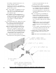
6. Connecting fi eld wiring, refer to Figures 5, 6 and 19.
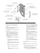
Step a. 120 volt power supply fi eld wiring will
enter internal junction box through 7/8" dia.
knockout in jacket rear panel, see Figure 5.
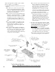
Step b. Locate the black and white harness wires
labeled "120V Power Supply" inside internal
junction box, see Figure 6. Using wire nuts,
connect the 120 volt power supply fi eld wires to
the harness wires. Connect the fi eld ground wire
to the green grounding screw located in bottom
of internal junction, refer to Figures 6 and 20.
Step c. 24V thermostat fi eld wiring will enter
internal junction box through 5/16" snap bushing
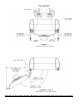
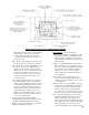
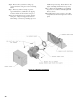
Figure 10: Piping Arrangement for Drain Valve and Indirect Water Heating Return
located on rear panel adjacent to 7/8" dia.
knockout for power supply.
Step d. Locate the two (2) brown wires labeled
"24V Thermostat" inside the internal junction
box, see Figure 6 (these wires originate from
"T-T" terminals in aquastat control and feed
into J-box through harness). Using wire nuts,
connect 24 volt fi eld thermostat wires to brown
wires in J-box.
Step e. Locate jacket top rear panel that was
removed earlier to gain access to internal
junction box. Position panel between side
panels, hold on a slight angle, engage tabs on
front fl ange of top rear panel with rectangle
slots on rear fl ange of top panel, refer to Figures
5 and 9.
NOTE: It may be necessary to lift up slightly
on top panel near slotted opening at supply
manifold to align tabs with rectangular slots on
fl anges.
Lower rear fl ange of jacket top rear panel down
over rear panel. Align holes and secure with
two (2) #8 x 1/2" lg. sheet metal screws.
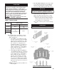
7. Installing stainless steel fl ueway baffl es. Baffl e
requirements differ from model to model, see
Table 2.
NOTE: Read caution statement before proceeding.