
Specifications


17
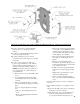
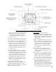
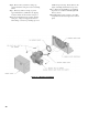
Figure 9: Return Manifold and Relief Valve Assembly Details
Place a wrench on the hex nut portion and
tighten manifold until the return pipe orientation
is correct for your installation and the joint is
water tight.
Step b. Install relief valve using 3/4" NPT tapping
on side of return manifold. Relief valve must
be installed in vertical position. If orientation of
return manifold is for:
• 1-1/2" NPT vertical return piping - Install
3/4" NPT x 90° street ell (not furnished)
into either the left or right side tapping on
return manifold. Install relief valve
vertically into street ell. Install 3/4" pipe
plug (not furnished) in tapping on
opposite side (see Figure 9).
• 1-1/2" NPT horizontal left or right side
return piping - Install relief valve vertically
in 3/4" NPT tapping located on top of
return manifold. Install 3/4" pipe plug (not
furnished) in bottom tapping as shown (see
Figure 9).
Step c. Pipe discharge of relief valve as shown in
Figures 13A and 13B. Installation of the relief
valve must be consistent with ANSI/ASME
Boiler and Pressure Vessel Code, Section IV.
GNINRAW
depipebtsumgnipipegrahcsidevlavfeileR
erevesfolaitnetopetanimileotroolfraen
erehwaeraynaniepiptonoD.snr
ub
ynallatsnitonoD.ruccodluocgnizeerf
.spacrosgulp,sevlavffo-tuhs
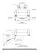
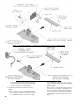
5. Install drain valve and indirect water heater return
piping, see Figure 10.
Step a. Apply pipe sealant to both ends of 1-1/4"
NPT x 5" lg. nipple. Thread nipple into 1-1/4"
NPT lower rear tapping on rear section.
Step b. Thread 1-1/4" x 1-1/4" x 3/4" NPT tee on
opposite end of 5" lg. nipple installed in Step a.
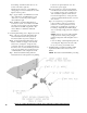
NOTE: Based on access for servicing and
location of sewer or fl oor drain, when tightening