
Specifications


16
from auxiliary limit control with harness socket
connector. Push connectors together until snap,
on side of connector, is locked in place.
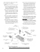
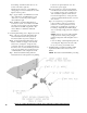
4. Install return manifold and relief valve, refer to
Figure 9.
Step a. Locate the cast iron return manifold with
injector nipple (installed). Apply thread sealant
to 2" NPT male threads. Insert injector nipple
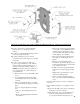
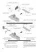
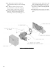
Figure 7: Optional Equipment - Low Water Cut-Off (LWCO) Control Assembly Details
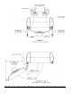
Figure 8: Optional Equipment - Auxiliary Limit Control Assembly Details
into 2" NPT upper rear tapping on rear section,
engage 2" NPT male threads on end of manifold
and hand tighten.
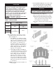
Note: Based on system return piping and access
to service boiler, see Figure 1 and Figures 13A
and 13B, predetermine if manifold orientation
is to be positioned for vertical, horizontal left or
horizontal right side return piping as shown in
Figure 9.