
Specifications


15
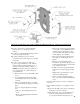
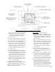
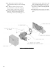
Figure 6: Internal Junction Box and Wiring Harness Details
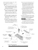
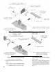
Mount the control box on the probe by aligning
the keyhole slots with the probe mounting
screws. Replace the wing nut. Secure the
control box by tightening wing nut and two (2)
mounting screws.
Step c. Remove snap-in plug from 7/8" dia. center
knockout, adjacent to aquastat control harness.
Step d. Insert three (3) wires with Molex connector
located on opposite end of LWCO harness
through 7/8" dia. knockout. Fish wires with
Molex connector to rear of internal junction box.
Insert snap-in conduit connector into 7/8" dia.
knockout, squeeze tabs on side of connector,
push into knockout and release tabs to lock
connector in place.
Step e. Inside internal junction box, locate wires
with mating LWCO socket connector labeled
"LWCO" (refer to Figure 6 for details of harness
located inside internal junction box). Remove
the factory installed socket plug jumper from
LWCO harness socket connector and discard.
Align mating halves of plug connector from
LWCO control with harness socket connector.
Push connectors together until snap on side of
connector is locked in place.
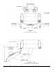
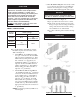
3. If required on this water boiler application,
install Auxiliary Dual Limit Control Kit, optional
equipment - Burnham P/N 100107-01, refer to
Figure 8. Also refer to instructions provided with
Auxiliary Dual Limit Control Kit.
If not required, proceed to Paragraph 4.
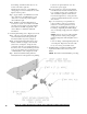
Step a. Locate 1/2" NPT x 1-1/2 immersion well.
Apply thread sealant to 1/2" NPT male threads.
Thread well into 1/2" NPT boss on left side of
supply manifold. Using hex head, tighten well
until water tight.
Step b. Locate L4080B Auxiliary Limit Control/
Harness Assembly. Loosen mounting screw on
side of case. Insert sensing bulb into immersion
well. Mount control on immersion well and
tighten screw to secure control in vertical
position with harness extending toward rear as
shown in Figure 8.
Step c. Remove snap-in plug from 7/8" dia.
knockout closest to supply manifold. Remove
locking ring from 90° conduit connector on end
of control harness.
Step d. Insert two (2) wires with Molex connector
located on end of auxiliary limit control harness
through 7/8" dia. knockout. Fish wires with
Molex connector to rear of internal junction
box. Insert 90° conduit connector into 7/8" dia.
knockout, secure to top panel with locking ring.
Step e. Inside internal junction box, locate wires
with mating auxiliary limit socket connector
labeled "Aux. Limit" (refer to Figure 6 for
details of harness located inside internal junction
box). Remove the factory installed socket plug
jumper from harness socket connector and
discard. Align mating halves of plug connector