IN S TAL L AT ION , OP E R AT IN G AN D S E R V IC E IN S T R U C T ION S F OR MP O 3 - PA S S O I L B O I L E R As an ENERGY STAR® Partner, Burnham Hydronics has determined that the MPO84, MPO147, MPO189 and MPO231 meet the ENERGY STAR® guidelines for Energy efficiency established by the United States Environmental Protection Agency (EPA). F o r s e r vi c e o r r e p a i r s to b o i le r, c a ll yo ur he a ti ng c o ntr a c to r o r o i l s up p li e r.
IMPORTANT INFORMATION - READ CAREFULLY All b o ile rs mu s t b e in s ta lle d in a c c o rd a n c e w ith N a tio n a l, S ta te a n d L o c a l P lu mb in g , H e a t in g a n d E le c t r ic a l C o d e s a n d t h e r e g u la t io n s o f t h e s e r v in g u t ilit ie s . T h e s e C o d e s a n d R e g u la tio n s ma y d iffe r fro m th is in s tru c tio n ma n u a l.
DANGER D O N OT s t o r e o r u s e g a s o lin e o r o t h e r fla m m a b le v a p o r s o r liq u id s in t h e v ic in it y o f t h is o r a n y o t h e r a p p lia n c e . WAR N IN G Im p r o p e r in s t a lla t io n , a d ju s t m e n t , a lt e r a t io n , s e r v ic e o r m a in t e n a n c e c a n c a u s e p r o p e r t y d a m a g e , p e r s o n a l in ju r y o r lo s s o f lif e .
WAR N IN G T h is b o ile r c o n t a in s v e r y h o t w a t e r u n d e r h ig h p r e s s u r e . D o n o t u n s c r e w a n y p ip e fit t in g s n o r a t t e m p t t o d is c o n n e c t a n y c o m p o n e n t s o f t h is b o ile r w it h o u t p o s it iv e ly a s s u r i n g t h e w a t e r i s c o o l a n d h a s n o p r e s s u r e .
TA B L E O F C O N T E N T S I. Pre-Installation ..................................... 8 VIII. System Start-Up..................................... 35 II. Packaged Boiler Assy.- Trim & Control... 10 IX. Maintenance & Service Instuction .......... 43 III. Water Boiler Trim & Piping ......... ........... 21 X. Boiler Cleaning...................................... 45 IV. Indirect Water Heater Piping..... .............. 25 XI . Trouble Shooting.................................. . 47 V. Venting .
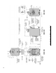
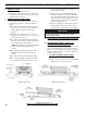
Figure 1: MPO 84 Thru MPO 231 Water Boiler
2 8 - 5 /8 " 3 4 - 5 /8 " M P O1 8 9 M P O2 3 1 0 .6 0 1 .0 5 1 .3 5 1 .6 5 M P O8 4 M P O1 4 7 M P O1 8 9 M P O2 3 1 GP H 231 189 147 84 MB H 7" 6" 6" 5" "C" 203 167 129 74 D OE He a ti ng C a p a c i ty M B H B urne r C a p a c i ty TABLE 1B: RATING DATA B o i le r Mo d e l No . 36" 30" 24" 24" "B" D i me ns i o ns S e e F i g ure 1 1 7 .8 4 1 4 .4 6 11 .0 8 7 .7 0 Wa te r C o nte nt Ga llo ns 3 4 .2 9 2 7 .2 9 2 0 .2 9 1 3 .
SECTION I: PRE-INSTALLATION A. INSPECT SHIPMENT carefully for any signs of damage. 1. All equipment is carefully manufactured, inspected and packed. Our responsibility ceases upon delivery of crated boiler to the carrier in good condition. 2. Any claims for damage or shortage in shipment must be filed immediately against the carrier by the consignee. No claims for variances from, or shortage in orders, will be allowed by the manufacturer unless presented within sixty (60) days after receipt of goods.
C. PROVIDE COMBUSTION AND VENTILATION AIR. Local and National Codes may apply and should be referenced. WARNING Ad e q u a t e c o m b u s t i o n a n d v e n t i l a t i o n a ir m u s t b e p r o v id e d t o a s s u r e p r o p e r c o m b u s t io n a n d t o m a in t a in s a fe a m b ie n t a ir t e m p e r a t u r e s . D o n o t in s t a ll b o ile r w h e r e g a s o lin e o r o t h e r fla m m a b le v a p o r s o r liq u id s , o r s o u r c e s o f h y d r o c a r b o n s ( i.e .
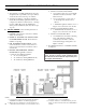
SECTION II: PACKAGED BOILER ASSEMBLY - TRIM & CONTROLS A. REMOVE CRATE. 1. Remove all fasteners at crate skid. 2. Lift outside container and remove all other inside protective spacers and bracing. Remove burner and miscellaneous parts cartons. B. REMOVE BOILER FROM SKID. 1. To reduce the risk of damage to boiler jacket, use the following procedure to remove from skid, see Figure 3: Step 1. Boiler is secured to base with (4) 5/16" cap screws, (2) in front and (2) in rear of shipping skid, see Figure 3.
Figure 4A: Partial Front View - Burner Swing Door Mounted to Boiler - Fully Closed and Secured Step 2. Loosen and remove right side latching hardware (5/16" x 1-3/4" lg. tap bolt and washer). Step 3. Remove left side latching hardware (5/16" x 1-3/4" lg. tap bolt and washer). Step 4. Disconnect burner power cord from receptacle located in lower right corner of jacket front panel. Step 5.
Figure 4B: Top View - Burner Swing Door Mounted to Cast Iron Block Assembly (Jacket Removed for Clarity) 12
(protruding from the bottom of the front section casting - see Figure 4A). E. INSPECT SWING DOOR INSULATION AND ROPE GASKET. Step 3. Use one hand to help hold door in position by lifting up on rear burner housing or applying pressure directly to the door while re-installing the securing hardware with your opposite hand. Always install right side latching hardware (5/16" x 1-3/4" lg. tap bolt and flat washer) first, then install left side hinge hardware (5/16" x 1-3/4" lg. tap bolt and flat washer) second.
5 thru 12) throughout the assembly sequence outlined below as it applies to your installation. 1. Install supply manifold and aquastat control, refer to Figure 5. Step a. Remove two (2) #8 x 1/2" lg. sheet metal screws securing jacket top rear panel to jacket rear panel. Slightly lift and pull jacket top rear panel away from jacket top panel to gain access to internal J-box wiring harness. Step b. Locate the cast iron supply manifold shown in Figure 5. Apply thread sealant to 1-1/2" NPT male threads.
Figure 6: Internal Junction Box and Wiring Harness Details Mount the control box on the probe by aligning the keyhole slots with the probe mounting screws. Replace the wing nut. Secure the control box by tightening wing nut and two (2) mounting screws. Step c. Remove snap-in plug from 7/8" dia. center knockout, adjacent to aquastat control harness. Step d. Insert three (3) wires with Molex connector located on opposite end of LWCO harness through 7/8" dia. knockout.
Figure 7: Optional Equipment - Low Water Cut-Off (LWCO) Control Assembly Details Figure 8: Optional Equipment - Auxiliary Limit Control Assembly Details from auxiliary limit control with harness socket connector. Push connectors together until snap, on side of connector, is locked in place. 4. Install return manifold and relief valve, refer to Figure 9. Step a. Locate the cast iron return manifold with injector nipple (installed). Apply thread sealant to 2" NPT male threads.
Place a wrench on the hex nut portion and tighten manifold until the return pipe orientation is correct for your installation and the joint is water tight. Step b. Install relief valve using 3/4" NPT tapping on side of return manifold. Relief valve must be installed in vertical position. If orientation of return manifold is for: • 1-1/2" NPT vertical return piping - Install 3/4" NPT x 90° street ell (not furnished) into either the left or right side tapping on return manifold.
these fittings, determine if drain valve is to be located on the left or right side. Tighten nipple and tee into 1-1/4" NPT lower rear tapping on rear section until joints are water tight for desired position. Step c. Apply sealant to 3/4" NPT thread on drain valve. Thread into 3/4" NPT tapping on side outlet of tee. Use hex nut portion to tighten valve until water tight. Step d. If Alliance ™ Indirect Water Heater is connected to system, do not install 1-1/4" NPT pipe plug.
CAUTION T h e s e b a ffle s w ill g e n e r a t e h ig h e r e ffic ie n c ie s a n d lo w e r s t a c k t e m p e r a t u r e s . U n d e r c e r t a in c o n d it io n s , a lo w e r g r o s s s t a c k t e m p e r a t u r e e n t e r in g t h e c h im n e y h a s t h e p o t e n t ia l t o b e c o o le d b e lo w t h e d e w p o in t a n d c r e a t e c o n d e n s a t e o n in t e r io r s u r fa c e s .
Step d. Remove three (3) 5/16-18 x 3/4 lg. cap screw from burner swing door used for mounting burner. Step e. Thread (1) 5/16-18 x 3/4 lg. cap screw, approximately three (3) full turns, into tapping located at 12:00 o'clock on burner swing door. Step f. Insert oil burner into the opening of burner swing door. Align and engage keyhole slot in burner flange over head of protruding cap screw installed in previous Step. Rotate burner to the right to lock flange behind head of cap screw. Step g.
SECTION III: WATER BOILER PIPING NOTICE F a ilu r e t o p ip e b o ile r a s s p e c ifie d in t h is m a n u a l m a y r e s u lt in e x c e s s iv e s y s t e m n o is e . A. EVALUATE THE EXISTING WATER SYSTEM. Design a piping system and install boiler which will prevent oxygen contamination of boiler water and frequent water additions. 1. There are many possible causes of oxygen contamination such as: a. Addition of excessive make-up water as a result of system leaks. b.
Figure 13A: Water Boiler Piping for Circulator Zoned Heating System - Supply Side Circulator
Figure 13B: Preferred Water Boiler Piping for Zone Valve Zoned Heating System - Supply Side Circulator
To perform a long term pressure test including the boiler, ALL trapped air must first be removed from the boiler. A loss of pressure during such a test, with no visible water leakage, is an indication that the boiler contained trapped air.
SECTION IV: INDIRECT WATER HEATER PIPING A. CONNECT ALLIANCE™ INDIRECT WATER HEATER PIPING as shown in Figures 15A and 15B. Also refer to Figures 13A and 13B. 1. Refer to Alliance™ manual for additional information.
SECTION V: VENTING A. CHIMNEY VENTING 1. Chimney venting is an important part of a safe and efficient oil fired appliance system. Contact your local fire and building officials on specific requirements for restrictions and the installation of fuel oil burning equipment.
Figure 16: Recommended Vent Pipe Arrangement and Chimney Requirements Figure 17: Proper and Improper Locations of Draft Regulator 27
2. Type B Chimney Connector - a type B chimney connector can be used to transmit the flue gases provided flue gas temperature entering the chimney connector is greater than 310°F. 3. Type L Chimney Connector - a type L vent or other suitable material shall be used for a chimney connector if the temperature or exiting temperature is less than 310°F. D AN GE R An y s i g n s o f c o n d e n s a t e s e e p a g e a t t h e b a s e o f t h e c h im n e y s h a ll b e in s p e c t e d im m e d ia te ly.
WARNING R e m o v e t h e b a ffle s if t h e r e a r e a n y s ig n s o f c o n d e n s a t io n in t h e c h im n e y o r c h im n e y c o n n e c to r. C o n s u lt w ith y o u lo c a l c h im n e y p r o fe s s io n a l fo r r e c o m m e n d a t io n s . E. MINIMUM CLEARANCES See Figure 2 for details regarding clearances to combustibles for the boiler. F.
c. Mount the vacuum relief valve into the tee and fasten with a screw and nut in collar tabs. To ensure proper operation, the gate must be level across the pivot point and plumb. Refer to vacuum relief valve manufacturer's instructions. 5. Install remainder of air intake, securing each joint with at least three (3) sheet metal screws evenly spaced. 6. Install air intake terminal. See Figure 19.
SECTION VI: ELECTRICAL D AN G E R P o s it iv e ly a s s u r e a ll e le c t r ic a l c o n n e c t io n s a r e u n p o w e r e d b e fo r e a t t e m p t in g in s t a lla t io n o r s e r v ic e o f e le c t r ic a l c o m p o n e n t s o r c o n n e c t io n s o f t h e b o ile r o r b u ild in g . L o c k o u t a ll e le c t r ic a l b o x e s w it h p a d lo c k o n c e p o w e r is t u r n e d o ff.
A call for heat by the thermostat energizes the L7248C control which in turn energizes the primary control to turn on the burner. The burner will operate in the following sequence: Prepurge for the first 10 seconds; fire until the thermostat is satisfied or the limit setting on the operating (high) limit is reached; post-purge for the last 10 seconds. The circulator will operate as long as the thermostat is calling for heat.
SECTION VII: OIL PIPING A. GENERAL WAR N IN G 1. Use flexible oil line(s) so the burner swing door can be opened without disconnecting the oil supply piping. 2. A supply line fuel oil filter is recommended as a minimum for all firing rates but a pleated paper fuel oil filter is recommended for the firing rates below 1.0 gph to prevent nozzle fouling. 3. Use Flared fittings only. Cast iron fittings cannot be used.
C. TWO PIPE OIL LINES 1. For two piped systems, where more lift is required, the two-stage fuel unit is recommended. Table 3 (two-stage) and Table 4 (single-stage) show allowable lift and lengths of 3/8 inch and 1/2 inch OD tubing for both suction and return lines. Refer to Figure 22. 2. Follow the oil pump manufacturer’s recommendations on the proper connections for a two pipe system. Some manufacturers require the insertion of a bypass plug.
SECTION VIII: SYSTEM START-UP WAR N IN G Al l b o i l e r s e q u i p p e d w i t h b u r n e r s w i n g d o o r h a v e a p o t e n t i a l h a z a r d w h i c h c a n c a u s e s e v e r e p r o p e r ty d a m a g e , p e r s o n a l in ju r y o r lo s s o f life if ig n o r e d . B e fo r e o p e n in g s w in g d o o r, tu r n o ff s e r v ic e s w itc h to b o ile r to p r e v e n t a c c id e n ta l fir in g o f b u r n e r o u ts id e th e c o m b u s tio n c h a m b e r.
any key pressed, the display will enter a dim display mode. To return to the bright display mode, simply press any key. D. ADJUST CONTROL SETTINGS with burner service switch turned “ON” and room thermostat set 10° below room temperature. 1. Adjustment and display modes of the L7248C Oil Electronic Aquastat Controller. Text a. On the L7248C, the overall range of the High Limit is from 180°F to 240°F (82°C to 116°C). b. Set the High Limit (designated HL) on the L7248C Aquastat Control at 180°F.
high limit automatically resets after the water temperature drops past the setpoint and through the differential. 3. TURN ‘ON’ BURNER service switch and allow burner to run until oil flows from vent fitting in a SOLID stream without air bubbles for approximately 10 seconds. NOTE: For Primary Control "Pump Priming Cycle" details, see Paragraph I, No. 2., Step a., Item ii . 4. Close vent fitting and burner flame should start immediately after prepurge is completed.
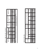
Figure 27: "L1/L2" and "V1" Head Electrode Positioning and Gun Setting (Beckett AFG)
smoke tester and adjust air for minimum smoke (not to exceed #1) with a minimum of excess air. Make final check using suitable instrumentation to obtain a CO2 of 11.5 to 12.5% with draft of zero inches water column ("w.c.) (water gauge) in canopy. These settings will assure a safe and efficient operating condition. If the flame appears stringy instead of a solid fire, try another nozzle of the same type. Flame should be solid and compact.
• To reset from Restricted Mode: Press and hold the reset button for 30 seconds. When the LED flashes twice, the device has reset. v. T-T Jumper: Select models have preinstalled T-T jumper resistor. To remove jumper, if applicable, use side-cutting pliers to cut jumper (See Figure 28). vi. Diagnostic LED: The indicator light on oil primary control provides lockout, recycle and cad cell indications as follows: • Flashing at 1 Hz (½ second on, ½ second off): system is locked out or in Restricted Mode.
Hydrolevel 1150 probe low water cut-off operational test procedure: ignitor, clean face of cad cell and see that cell is securely in socket. Check gasket around perimeter of ignitor lid for proper seal. If gasket is missing or damaged, replace gasket. Room light can effect cad cell resistance. Reset safety switch. a. Before raising the water level above the Model 1150, turn on power to the boiler and set the thermostat to call for heat.
Im p o r t a n t P r o d u c t S a fe t y In fo r m a t io n R e fr a c t o r y C e r a m ic F ib e r P r o d u c t Warning: This product contains refractory ceramic fibers (RCF). RCF has been classified as a possible human carcinogen. After this product is fired, RCF may, when exposed to extremely high temperature (>1800F), change into a known human carcinogen. When disturbed as a result of servicing or repair, RCF becomes airborne and, if inhaled, may be hazardous to your health.
SECTION IX: MAINTENANCE AND SERVICE INSTRUCTIONS A. MAINTENANCE OF LOW WATER CUTOFF DEVICES (when installed) See Section XIV Appendix for LWCO Installation Instructions tenacious lime deposits. The most stubborn deposits may be removed from the probe by using a diluted amount, 3 parts of water to 1 part of phosphoric acid (H2PO4). WARNING CAUTION P r o b e t y p e lo w w a t e r c u t - o ff d e v ic e s r e q u ir e a n n u a l in s p e c t io n a n d m a in t e n a n c e .
D AN G E R As s u r e t h a t t h e b o i l e r i s a t z e r o p r e s s u r e b e fo r e r e m o v in g t h e r e lie f v a lv e . Op e n t h e s a fe t y v a lv e t o r e lie v e a ll in t e r n a l p r e s s u r e p r io r t o p r o c e e d in g . S a fe t y v a lv e d is c h a r g e p ip in g m u s t b e p ip e d s u c h t h a t t h e p o t e n t ia l fo r b u r n s is e lim in a t e d . c. Remove relief valve using extreme care to avoid damaging it. d.
SECTION X: BOILER CLEANING WARNING Al l b o i l e r c l e a n i n g m u s t b e c o m p l e t e d w i t h b u r n e r s e r v i c e s w i t c h t u r n e d o f f . B o i l e r s e q u i p p e d w it h b u r n e r s w in g d o o r h a v e a p o t e n t ia l h a z a r d w h ic h c a n c a u s e s e v e r e p r o p e r t y d a m a g e , p e r s o n a l in ju r y o r lo s s o f life if ig n o r e d .
Figure 30: Cleaning of Boiler Flueways WARNING T h e b o ile r m u s t b e c o n n e c t e d t o a n a p p r o v e d c h im n e y in g o o d c o n d it io n . S e r io u s p r o p e r t y d a m a g e c o u ld r e s u lt if th e b o ile r is c o n n e c te d to a d ir ty o r in a d e q u a te c h im n e y.
SECTION XI: TROUBLE SHOOTING A. COMBUSTION 1. NOZZLES — Although the nozzle is a relatively inexpensive device, its function is critical to the successful operation of the oil burner. The selection of the nozzle supplied with the MPO boiler is the result of extensive testing to obtain the best flame shape and efficient combustion. Other brands of the same spray angle and spray pattern may be used but may not perform at the expected level of CO2 and smoke.
b. Air leaking into oil line causing flame out. c. Defective nozzle causing flame to be erratic. d. Excessive airflow or draft causing flame to leave burner head. e. Excessive back pressure causing flame to be erratic. 3. Control locks out after Trial For Ignition (TFI). a. No oil to burner. b. Shorted electrodes. c. Nozzle clogged. Note: The Safety Monitoring Circuit (SMC) is designed to provide lockout in the event of a stuck or welded motor relay.
SERVICE RECORD DATE SERVICE PERFORMED 49
Bare Boiler Assembly
Ite m D e s c r i p ti o n No . P a rt No . M P O8 4 M P O1 4 7 M P O1 8 9 M P O2 3 1 1 . B AR E B OIL E R AS S E MB LY 1A F ro nt S e c ti o n, Ma c hi ne d 100060-01 1 1 1 1 1B C e nte r S e c ti o n, Ma c hi ne d 100061-01 --- 1 2 3 1C Re a r S e c ti o n, Ma c hi ne d 100062-01 1 1 1 1 1D S li p Ni p p le , 2 2 -B Ste e l 806600375 2 4 6 8 Up p e r Ti e Ro d , 3 /8 " -1 6 x 1 0 " L g . 80861071 1 --- --- --- Up p e r Ti e Ro d , 3 /8 " -1 6 x 1 6 " L g .
Bare Boiler Assembly
Ite m D e s c r i p ti o n No . P a rt No . M P O8 4 M P O1 4 7 M P O1 8 9 M P O2 3 1 1 . B AR E B OIL E R AS S E MB LY (C o n tin u e d ) B urne r S wi ng D o o r Ins ula ti o n (L e s s P o c k e ts ) 1 0 0 0 7 1 -0 1 1 1 1 1 B urne r S wi ng D o o r Ins ula ti o n (Wi th P o c k e ts ) 1 0 0 0 7 4 -0 1 1 1 1 1 1T 5 /8 " D i a . Ro p e Ga s k e t - B urne r S wi ng D o o r 1 0 0 0 9 7 -0 1 1 1 1 1 1U 1 /8 " D i a .
Jacket Assembly
Ite m D e s c r i p ti o n No . P a rt No . M P O8 4 M P O1 4 7 M P O1 8 9 M P O2 3 1 1 0 0 0 0 7 -0 1 1 1 1 1 2 .
MPO84 Thru MPO231 Water Boilers - Trim and Controls
ITE M D E S C RIP TION NO. P a rt No . M P O8 4 M P O1 4 7 M P O1 8 9 M P O2 3 1 3 . MP O8 4 T h ru MP O2 3 1 WAT E R B OIL E R S - T R IM AN D C ON T R OL S B e c k e tt A F G Oi l B urne r w/Ga s k e t fo r: 3A MP O8 4 Sp e c No . B C B 7 7 0 2 1 0 0 0 5 2 -0 1 1 --- --- --- MP O1 4 7 Sp e c No . B C B 7 7 0 3 1 0 0 0 5 3 -0 1 --- 1 --- --- MP O1 8 9 Sp e c No . B C B 7 7 0 4 1 0 0 0 5 4 -0 1 --- --- 1 --- MP O2 3 1 Sp e c No .
Beckett AFG Burner
BECKETT OIL BURNER PART NOS. FOR MPO SERIES BOILERS NOTE: When ordering parts always give the serial and model numbers shown on the boiler and burner. Also provide the name of the part(s) and part number as listed below.
XIV. LOW WATER CUT-OFF (LWCO) ON HOT WATER BOILERS WAR N IN G D O N OT AT T E M P T to c u t fa c to r y w ir e s to in s ta ll a n a fte r m a r k e t L o w Wa te r C u t Off (LW C O). On ly u s e c o n n e c tio n s s p e c ific a lly id e n tifie d fo r L o w Wa te r C u t Off. In a ll c a s e s , fo llo w th e L o w Wa te r C u t Off (LW C O) m a n u fa c tu r e r ' s in s tr u c tio n s .
Figure A2: LWCO Location
SERVICE RECORD DATE 62 SERVICE PERFORMED
0 .6 0 1 .0 5 1 .3 5 1 .6 5 M P O8 4 M P O1 4 7 M P O1 8 9 M P O2 3 1 V 1 (3 ) V 1 (0 ) L1 L2 H ead Ty p e ( s e t t in g ) 7 7 7 61 2 2 1 0 Air Air S h u tte r B and ( s e t t in g ) ( s e t t in g ) 150 150 150 150 0 .8 5 x 6 0 B D e la va n 1 .1 0 x 6 0 B Ha g o 1 .3 5 x 6 0 B Ha g o N o z z le 2 nd 2 nd 2 nd 3 rd 18 39 65 52 0 0 0 0 0 0 0 0 B a f f le s 0 .0 5 0 0 .0 4 0 0 .0 4 0 0 .0 1 0 B a f f le s 0 .0 3 0 0 .0 3 0 0 .0 2 0 0 .
Limited Warranty FOR RESIDENTIAL CAST IRON WATER BOILERS Subject to the terms and conditions set forth below, U.S. Boiler™ Co., Inc. Lancaster, Pennsylvania hereby extends the following limited warranties to the original owner of a residential grade water boiler manufactured and shipped on or after July 1,1991: ONE YEAR LIMITED WARRANTY ON RESIDENTIAL GRADE WATER BOILERS U.S. Boiler Co., Inc.