
Instruction manual

88
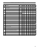
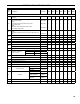
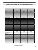
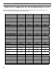
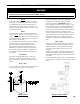
TABLE 12: BURNER SPECIFICATIONS
Boiler
Model
Firing
Rate
GPH
Beckett AFG Carlin Riello
Settings
1
Nozzle
2
Pump
Pressure
Burner
Model
Settings
1
Nozzle
2
Pump
Pressure
Burner
Model
Settings
1
Nozzle
Pump
Pressure
Head
(Setting)
Air
Shutter
Air
Band
GPH x
Angle
Type
Head
Bar
Air
Band
GPH x
Angle
Type
Air
Gate
Turbulator
GPH x
Angle
Type
V8H3S 0.75 L1 10 2 0.60 x 60A 140
EZ-1HP
0.60/0.65 0.53 0.60 x 60B 150 40-F5 2.25 1.0 0.70 x 90B 145
V8H3W 1.05 L1 7 1 0.85 x 60A 140 0.75 0.65
0.85 x 70B
Hago
150 40-F5 2.8 1.0 0.90 x 80B 145
V8H4S 1.05 V1 (0) 7 1 0.85 x 60A 140 0.85/1.00 0.75 0.85 x 60B 150 40-F5 3.75 1.0 0.90 x 80B 145
V8H4W 1.35 V1 (0) 10 2
1.10 x 60B
Hago
140 1.10/1.25 0.85 1.10 x 60B 150 40-F5 3.3 3.0 1.20 x 80B 145
V8H5S 1.35 V1 (0) 10 5 1.10 x 60B 140 1.10/1.25 0.80 1.10 x 60B 150 40-F5 5.5 2.0 1.20 x 80B 145
V8H5W 1.65 V1 (2) 10 5 1.35 x 60B 140 1.35/1.50 1.35 1.35 x 60B 150 40-F5 5.2 4.0 1.35 x 70B 145
V8H6S 1.65 V1 (2) 10 3 1.35 x 60B 140 EZ-2HP 1.50 1.75 1.35 x 60A 170 40-F10 3.2 3.0 1.50 x 45B 145
V8H6W 1.90 V1 (3) 10 3.5 1.50 x 45B 160 EZ-66 5 100% 1.65 x 60B 140 40-F10 3.7 2.0 1.65 x 60B 145
V8H7S
V8H7W
2.10 V1 (4) 10 3
1.65 x 45B
HAGO
170
102CRD-3
3 50% 1.75 x 60B 140 40-F10 4.0 4.0 2.00 x 45B 145
V8H8S
V8H8W
2.35 V1 (4) 10 5
1.75 x 45B
HAGO
170 4 50% 2.00 x 60B 140 40-F10 4.0 5.0 2.00 x 60B 175
V8H9S
V8H9W
2.60 V1 (6) 10 7
2.00 x 45B
HAGO
170 5 100% 2.25 x 70B 140 40-F10 7.0 5.0
2.25 x 60P
HAGO
145
1
All burners utilize Delavan nozzles unless otherwise noted.
2
Single stage fuel pump is standard, two stage fuel pump is optional. Burner manufacturer has preset single stage fuel pump to settings shown in table above.
Two stage fuel pump is factory set at 140 PSI and must be readjusted to settings shown above during burner start-up.
SECTION XVII: BURNER SPECIFICATIONS