
Instruction manual

37
A. GENERAL VENTING GUIDELINES
1. Vent system installation must be in accordance
with these instructions and applicable provisions of
local building codes. Contact local building or re
ofcials about restrictions and installation inspection
in your area.
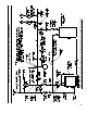
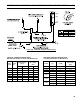
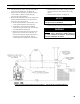
2. The V8H is designed to be vented into a reclay
tile-lined masonry chimney or chimney constructed
from type L vent or a factory built chimney that
complies with the type HT requirements of UL103.
The chimney and vent pipe shall have a sufcient
draft at all times, to assure safe proper operation
of the boiler. See Figure 18 for recommended
installation.
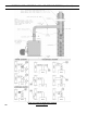
a. Install a draft regulator (supplied with boiler)
following the instructions furnished with the
regulator. See Figure 19 for alternate draft
regulator locations.
b. For Models V8H4W and V8H6W, the minimum
recommended round chimney size from Table
1B is one size larger than the smokebox outlet.
For a vertical vent, place the increaser on the
smokebox outlet collar. Otherwise, locate the
increaser in the horizontal vent at the entrance to
the chimney.
c. With any new or replacement installation the
chimney has to be considered. Chimneys that
have a high heat loss may become less suitable
as the heat loss of the home goes down and the
efciency of the boiler installed goes up. Most
homes have a chimney appropriate for the fuel
and the era in which the home was built. That
may have been a coal red or an inefcient oil
red boiler built into a home without insulation
or storm windows. With increasing fuel prices
that home probably has been insulated and tted
with storm windows so that the heat loss of the
home has been reduced. This requires less fuel to
be burned and sends less heat up the chimney.
A new boiler probably has a higher efciency
than the boiler being replaced. That probably
means that the stack temperature from the
new boiler will be lower than that from the
old boiler and with less room air being drawn
up the chimney to dilute the stack gases. The
combination of a large uninsulated chimney,
reduced ring rate, reduced ring time, lower
stack temperature and less dilution air can, in
some cases, contribute to the condensing of small
amounts of water vapor in the chimney. Such
condensation, when it occurs, can cause chimney
deterioration. In extreme cases, the chimney
may have to be lined to insulate the chimney and
thus prevent the condensation. The addition of
dilution air into the chimney may assist in drying
the chimney interior surfaces.
A massive chimney on a cold, or exposed outside
wall may have produced adequate draft when it
was red with a higher input and greater volumes
of heated gases. With reduced input and volume,
the draft may be severely affected. In one
instance our research showed a new chimney of
adequate sizing produced only .035" W.C. after
30 minutes of continuous ring at 13.0% CO
2
.
Outside wall chimneys take longer to heat up
and can have .00" W.C. draft at burner start-
up. You may have to consider a special alloy
chimney ue liner with insulation around it and a
stabilizing draft cap or even a draft inducing fan
in severe cases.
d. For the same reasons as in c. above, heat
extractors mounted into the breeching are not
recommended.
3. For minimum clearances to combustible materials
refer to Figure 2.
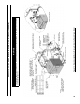
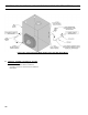
B. OPTIONAL AIR INTAKE PIPING
INSTALLATION - Outdoor air for combustion may
be provided with an optional U.S. Boiler Company
V8H™ Fresh Air Accessory Kit (ONLY AVAILABLE
ON BECKETT BURNERS, with plastic cover
application, P/N 102119-01), refer to Figure 20.
Refer to Fresh Air Accessory Kit Instructions for
installation and air intake piping details.
WARNING
DO NOT reduce size of air intake pipe.
Read, understand and follow combustion air
instruction restrictions contained in the Pre-
Installation Section of this manual.
1. General
a. Use 4 inch diameter, single wall galvanized
metal pipe and ttings available at most heating
distributors for air intake piping. Maximum
allowable air intake length is 50 equivalent feet.
Each elbow is equal to 6 equivalent feet.
WARNING
DO NOT exceed maximum allowable air intake
length.
b. Start at Burner. Work toward air intake terminal.
c. Maintain minimum of ¼ inch per foot slope in
horizontal run to air intake terminal. Slope down
toward air intake terminal.
d. Seal all joints gas-tight, using silicone caulk or
self-adhesive aluminum tape.
SECTION VIII: VENTING AND AIR INTAKE PIPING