
Instruction manual

22
5. Install oat-type LWCO, if so equipped.
See Figures 5 and 9.
a. Install nipples and unions in "D" Tappings.
b. Mount hardware to low water cut-off body.
Install assembly.
c. Install water gage glass on low water cut-off
assembly's tee ttings.
6. Install Pressure Limit Control.
a. Float LWCO only: Remove ¼" NPT plug from
top of Low Water Cut-Off. Install Syphon and
Limit into this tapping. See Figure 9.
b. Probe LWCO only: Install Limit in Tapping "A"
using ¾" NPT x 3" long nipple, ¾" NPT elbow,
¾" NPT x ¼" NPT bushing, and syphon. See
Figures 5 and 10.
c. DO NOT tighten the limit by holding the case;
apply a wrench to the brass hex below the case.
d. An L404F pressure limit does not require
leveling.
7. Connect the eld wiring to the LWCO or the
R8239A Control Center/J-box, or burner disconnect
J-box.
a. If equipped with tankless heater, connect eld
wiring from the aquastat control to the R8239A
Control Center transformer terminals or oil
burner primary control's "T-T" terminals.
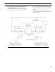
Make the wiring connections as shown in
appropriate wiring diagram, refer to Figure 22,
23A, 23B, 24A or 24B.
Note: DO NOT remove "T-T" jumper unless
wiring diagram indicates a direct connection
from thermostat and/or tankless heater aquastat
control to the oil burner primary control's "T-T"
terminals.
Also refer to Section XI, Paragraph I, Item 2,
"Verify Oil Primary Control" for more details.
b. Refer to Paragraph R for details on use of
burner disconnect junction box provided with all
knockdown boiler builds.
P. INSTALL TRIM AND CONTROLS WITH
CARLIN BURNERS.
Water boilers Only (see Figures 1A, 1B, 1C and 5).
Follow instructions in Paragraph N, Steps 1 through 7.
Steam Boilers Only (see Figures 1D and 5).
Follow instructions in Paragraph O, Steps 1 through 6.
7. Connect Field Wiring
a. Steam Boiler with Hydrolevel CG450 LWCO,
Carlin Burner.
Connect the eld wiring to the R8239A Control
Center. If equipped with tankless heater, connect
eld wiring from the aquastat control to the
R8239A Control Center’s “R-G” terminals.
Make the wiring connections as shown in
Figure 22.
b. Steam Boiler with McDonnell & Miller
PS-801 or McDonnell & Miller 67 LWCO,
Carlin Burner.
Connect the eld wiring to the LWCO or the
burner disconnect J-box. If equipped with
tankless heater, connect eld wiring from
the aquastat control to the oil burner primary
control’s “T-T” Terminals. Make the wiring
connections as shown in appropriate wiring
diagram, refer to Figure 23A, 23B, 24A or 24B.
Note: DO NOT remove "T-T" jumper unless
wiring diagram indicates a direct connection
from thermostat and/or tankless heater aquastat
control to the oil burner primary control's "T-T"
terminals.
Also refer to Section XI, Paragraph I, Item 2,
"Verify Oil Primary Control" for more details.
SECTION III: KNOCKDOWN BOILER ASSEMBLY (continued)
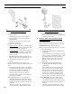
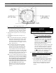
Figure 9: Float-Type Low Water Cut-Off and
Pressure Limit Installation
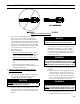
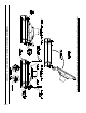
Figure 10: Pressure Limit Installation for Probe
LWCO Equipped Boilers