
Instruction manual

21
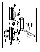
6. After control is installed and secured, remove
control cover. Then, remove knockout located
directly above factory connected limit harness on
right side ange of control. Insert circulator harness
end with attached fork terminals thru knockout hole
and push-in to engage harness connector into ange.
Connect wires to control terminals as follows - Blue
to C1 and White to C2 and tighten securely. Re-
install control cover.
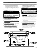
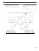
7. Connect Field Wiring.
a. Water boilers without tankless heater. Connect
the eld wiring to the aquastat control. Make the
wiring connections as shown on Figure 21A.
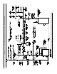
b. Water boilers with front or rear tankless heater.
Connect the eld wiring to the aquastat control.
Make the wiring connections as shown on Figure
21B.
c. Refer to Paragraph R for details on use of
burner disconnect junction box provided with all
knockdown boiler builds.
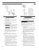
O. INSTALL TRIM AND CONTROLS WITH
BECKETT BURNER. - Steam Boiler Only
(see Figures 1D & 5).
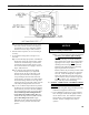
1. Thread the pressure gauge into the ¼” NPT tapping
"B", of the front section. Tighten with wrench
applied to the square shank of the gauge.
CAUTION
DO NOT apply pressure to the gauge case - this
may result in inaccurate readings.
2. Thread 1½” NPT x ¾” NPT bushing and a ¾” NPT
drain valve into the 1½” NPT tapping located in the
lower right corner of the front section. Tighten with
wrench.
NOTICE
Lower rear section Tapping "H" is used for
standard condensate return on steam boilers.
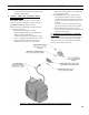
3. Thread safety valve, as shown in Figure 1D, into ¾"
NPT coupling and ¾” NPT x 8” nipple previously
installed in Paragraph H, No. 1, step b. Tighten
with wrench. Pipe discharge as shown in Figure
16. Installation of the safety (relief) valve must be
consistent with ANSI/ASME Boiler and Pressure
Vessel Code, Section IV.
WARNING
Safety valve discharge piping must be piped near
oor to eliminate potential of severe burns. DO
NOT pipe in any area where freezing could occur.
DO NOT install any shut-off valves, plugs or caps.
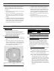
4. Install probe type Low Water Cut-Off (LWCO) if so
equipped.
a. Thread probe into ¾” NPT tapping "C" located
on the front section, down and to the right of
the pressure gauge. Slip the low water cut-off
(LWCO) control over the probe and clamp in
place. Connect the wire(s) between the probe and
control per the manufacturer’s instructions.
WARNING
Read the manufacturer's instructions packed with
the probe LWCO for proper pipe dope application.
DO NOT use Teon tape on probe threads. Use of
teon can render the probe LWCO inoperational.
b. Install the gauge glass using the two ½” NPT
tappings to the right of the probe LWCO.
SECTION III: KNOCKDOWN BOILER ASSEMBLY (continued)
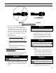
Figure 8: Limit Sensor Insertion