
Instruction manual

15
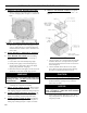
6. Install jacket top panel. (See Figure 6, Item 2F).
Place jacket top panel on boiler and secure to front,
rear and left side panels with #8 x ½” long sheet
metal screws.
7. Install jacket right side access panel. (See Figure
6, Item 2G). Align right side panel mounting holes
with front and rear panel holes. Secure with #8 x ½”
long sheet metal screws.
8. Attach the labels shipped in the instruction envelope
as follows:
a. Locate both the Rating Label and Combination
Warning Label (P/N 101265-01). Remove paper
backing from the labels and apply to the jacket
top panel in approximate locations shown in
(Figure 6, Item 2F).
b. On steam boilers only; locate Lowest Permissible
Water Level Plate (Form No. 1204 shipped in
Steam Trim Carton). Align plate with two 1/8"
diameter holes located near the front edge; in
line with the lower sight glass tapping, of the
jacket right side access panel. Attach plate with
two (2) #8 x 1/2" long sheet metal screws. (See
Figure 6, Item 2G).
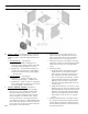
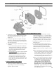
J. INSTALL BECKETT OIL BURNER.
(See Figure 7).
1. Check target wall and combustion chamber blanket.
If any damage or movement occurred during
shipment, replace as needed.
2. Locate burner swing door and hinge assembly
removed in Paragraph I, No. 1. Check the burner
swing door insulation and rope gasket for damage
and adhesion. If damaged, replace insulation or
gasket. If insulation or gasket is loose, reattach to
swing door with RTV 732 or 736 silicone caulk.
3. Install burner swing door in reverse order from
Paragraph I, No. 1.
4. Use the following procedure to properly close
and secure the burner swing door after it has been
removed and re-installed for Field Assembly
(Knockdown Boiler) or opened for inspection,
cleaning or eld service (refer to Figures 13A and
13B):
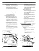
Step 1. Lift the door up unto the built-in cast ramp/
door rest (protruding from the bottom of the front
section casting - see Figure 13A), while rotating
the articulated hinge and door to the right and
engaging the slot (on right side of door) unto the
5/16" stud protruding from the front section.
Step 2. Use one hand to help hold door in position
by applying pressure directly to the door while
re-installing the securing hardware with your
opposite hand. Always install right side
latching hardware (5/16" ange nut and
at washer) rst, then install left side hinge
hardware (5/16" x 3-1/2" lg. hex head ange
bolt) second. Apply additional pressure while
hand tightening the hardware as far as possible,
then release the pressure.
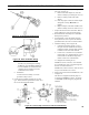
Figure 7: Oil Burner Installation (Beckett Burner Shown)
SECTION III: KNOCKDOWN BOILER ASSEMBLY (continued)