USER GUIDE & SERVICE MANUAL 1 Class ● UHWC024 ● 24” Wine Refrigerator
USER GUIDE & SERVICE MANUAL u-line.
USER GUIDE u-line.com WELCOME TO U-LINE Congratulations on your U-Line purchase. Your product comes from a company with over five decades of premium modular ice making, refrigeration, and wine preservation experience. U-Line creates products focused on functionality, style, and inspired innovations — paying close attention to even the smallest details. Applications include residential, outdoor, ADA height compliant, marine, and commercial.
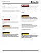
USER GUIDE u-line.com Safety and Warning ! DANGER NOTICE This unit contains R600a (Isobutane) which is a Please read all instructions before installing, flammable hydrocarbon. It is safe for regular operating, or servicing the appliance. use. Do not use sharp objects to expedite Use this appliance for its intended purpose only and follow these general precautions with those listed throughout this guide: defrosting.
USER GUIDE u-line.com Disposal and Recycling ! DANGER RISK OF CHILD ENTRAPMENT. Before you throw away your old refrigerator or freezer, take off the doors and leave shelves in place so children may not easily climb inside. If the unit is being removed from service for disposal, check and obey all federal, state, and local regulations regarding the disposal and recycling of refrigeration appliances, and follow these steps completely: 1. Remove all consumable contents from the unit. 2.
USER GUIDE u-line.com Environmental Requirements This model is intended for indoor/interior applications only and is not to be used in installations that are open/ exposed to natural elements. This unit is designed to operate between 50°F (10°C) and 100°F (38°C). Higher ambient temperatures may reduce the unit’s ability to reach low temperatures and/or reduce ice production on applicable models. For best performance, keep the unit out of direct sunlight and away from heat generating equipment.
USER GUIDE u-line.com Electrical ! WARNING SHOCK HAZARD — Electrical Grounding Required. Never attempt to repair or perform maintenance on the unit until the electricity has been disconnected. Never remove the round grounding prong from the plug and never use a two-prong grounding adapter. Altering, cutting or removing power cord, removing power plug, or direct wiring can cause serious injury, fire, loss of property and/or life, and will void the warranty.
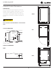
USER GUIDE u-line.com Cutout & Product Dimensions 23 15⁄16” (608 mm) PREPARE SITE Your U-Line product has been designed for either freestanding or built-in installation. When built-in, your unit does not require additional air space for top, sides, or rear. However, the front grille must NOT be obstructed, FRONT and clearance is required for an electrical connection in 34 1⁄8” to 35 1⁄8” (867 mm to 892 mm) 28” (711 mm) the rear.
USER GUIDE Side-by-Side Installation u-line.com 3. Place bracket over holes and attach to unit with two screws removed in step 2 using a T-25 Torx driver. Two units may be installed side-by-side. Cutout width for a side-by-side installation is the cutout Tighten screws fully. 4. Gently push units into position. Be careful not to dimension of a single unit times two. No trim kit is required. However, 1/4" (6 mm) of space entangle the electrical cord or water line, if applicable. 5.
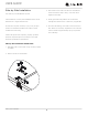
USER GUIDE u-line.com Anti-Tip Bracket 1. Slide unit out so screws on top of unit are easily accessible. 2. Remove the two screws from the opposite side of the hinge assembly using a T-25 Torx driver (see below). 3. Place bracket over holes and attach to unit with two screws removed in step 2 using a T-25 Torx driver. Tighten screws fully. 4. Gently push unit into position. Be careful not to entangle the electrical cord or water line, if applicable. 5.
USER GUIDE u-line.com General Installation INSTALLATION LEVELING INFORMATION 1. Use a level to 1. Plug in the power/electrical cord. 2. Gently push the unit into position. Be careful not to entangle the cord or water and drain lines, if confirm the unit is applicable. level. Level should 3. be placed along top Re-check the leveling, from front to back and side to edge and side edge side. Make any necessary adjustments. The unit’s top as shown.
USER GUIDE u-line.com Grille Installation REMOVING AND INSTALLING GRILLE ! WARNING Disconnect electric power to the unit before removing the grille. When using the unit, the grille must be installed. ! WARNING DO NOT touch the condenser fins. The condenser fins are SHARP and can be easily damaged. Removing the grille 1. Disconnect power to the unit. 2. Loosen the two screws (1). 3. Remove grille (2) from unit. Installing the grille 1.
USER GUIDE u-line.com Door Swing Wall 2-1/8" Min. (54 mm) 90° Door Swing Units have a zero clearance for the door to open 90°, when installed adjacent to cabinets. Stainless Steel models require 2-1/8" (54 mm) door clearance to accommodate the handle if installed next to a wall.
USER GUIDE u-line.com Door Adjustments REVERSING THE DOOR Location of the unit may make it desirable to mount the HINGE COVER door on the opposite side of the cabinet. Hinge cover included with the literature bag is optional. The hinge hardware will be removed and reinstalled on the opposite side of the cabinet. TO REVERSE THE DOOR To install hinge cover: 1. Press hinge cover squarely over hinge.
USER GUIDE 3. Remove door by tilting forward and lifting door off u-line.com Install top hinge and door: bottom hinge. Retain shoulder washers; they will be reused. 4. Top Hinge Right Side Insert arrow clips into holes Top Hinge Left Side Pivot Screw Remove bottom hinge: 1. Remove bottom hinge from cabinet using a T-25 TORX 1. install the pivot screw in the same hole from the screw driver to remove three screws. 2. Remove pivot screw from hinge, flip hinge over, and opposite surface.
USER GUIDE u-line.com Free Standing Kit Te free standing kit is an optional accessory (ULAFREESTANDS), used when unit is freestanding - not built into a cabinet. Available at u-line.com. To install the kit: 1. Remove grille (see GRILLE INSTALLATION section). 3. Align front hole wit hole in shell accessory, hole in base, and hole in grille. Tighten screw. 2. Place shell accessory over front and back of cabinet base, aligning holes of shell accessory with the holes on the base.
USER GUIDE u-line.com First Use Initial startup requires no adjustments. If the unit was turned off, press and hold for 5 seconds to turn unit on. See “Control Operation” section for more details. NOTICE Temperature displayed reflects actual temperature inside unit. If the temperature displayed is different than selected, the unit is progressing towards the selected temperature. Time to reach set point varies based upon ambient temperature, temperature of product loaded, door openings, etc.
USER GUIDE u-line.com Control Operation CONTROL FUNCTION GUIDE FUNCTION COMMAND NOTES ON/OFF Press and hold down for 5 seconds Unit will turn On or OFF Press and release to leave interior Leave interior light on light on for 3 hours; press again to After 3 hours, factory default is restored; light will turn on when door is open deactivate When the display is flashing, press Adjust Temperature Press or and release or to adjust the set point temperature.
USER GUIDE u-line.com Airflow and Product Loading NOTICE Restricting airflow may result in poor product AIRFLOW performance, product failure, and uneven internal External temperatures and may freeze contents.
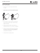
USER GUIDE Recommended Wine Storage Wine bottles can be stored on the racks or bottom as shown. u-line.com Bottom The bottom shelf of the unit is designed to hold up to six standard-size wine bottles. RACKS The racks are designed to hold a variety of bottle shapes and sizes including larger champagne and magnum bottles. Standard-Size Wine Bottles Large-Size Bottles Note: The racks are secured to the unit and are not designed to be removed.
USER GUIDE u-line.com Cleaning If any surface discoloring or rusting appears, clean it EXTERIOR CLEANING and a nonabrasive cloth. Always clean with the grain. Vinyl Clad (Black or White) Always finish with Claire® Stainless Steel Polish and Clean surfaces with a mild detergent and warm water solution. Do not use solvent-based or abrasive cleaners. quickly with Bon-Ami® or Barkeepers Friend Cleanser® Cleaner or comparable product to prevent further problems.
USER GUIDE u-line.com High ambient temperature and excessive humidity can also produce frost. ! CAUTION DO NOT use an ice pick or other sharp instrument to help speed up defrosting. These instruments can puncture the inner lining or damage the cooling unit. DO NOT use any type of heater to defrost. Using a heater to speed up defrosting can cause personal injury and damage to the inner lining. NOTICE The drain pan was not designed to capture the water created when manually defrosting.
USER GUIDE u-line.com Cleaning Condenser INTERVAL - EVERY SIX MONTHS To maintain operational efficiency, keep the front grille free of dust and lint, and clean the condenser when necessary. Depending on environmental conditions, more or less frequent cleaning may be necessary. ! WARNING Disconnect electric power to the unit before cleaning the condenser. NOTICE DO NOT use any type of cleaner on the condenser unit. Condenser may be cleaned using a vacuum, soft brush, or compressed air. 1.
USER GUIDE u-line.com Extended Non-Use VACATION/HOLIDAY, PROLONGED SHUTDOWN The following steps are recommended for periods of extended non-use: 1. Remove all consumable content from the unit. 2. Disconnect the power cord from its outlet/socket and leave it disconnected until the unit is returned to service. 3. If ice is on the evaporator, allow ice to thaw naturally. 4. Clean and dry the interior of the unit. Ensure all water has been removed from the unit. 5.
USER GUIDE u-line.com Troubleshooting • Evaporator: Refrigerant flowing through an evaporator may sound like boiling liquid. BEFORE CALLING FOR SERVICE • Condenser Fan: Air moving through a condenser may be heard. • Automatic Defrost Drain Pan: Water may be heard dripping or running into the drain pan when the unit is in the defrost cycle. If you think your U-Line product is malfunctioning, read the CONTROL OPERATION section to clearly understand the function of the control.
USER GUIDE CHECKING PRODUCT TEMPERATURE u-line.com Causes which affect the internal temperatures of the cabinet include: • Temperature setting. • Ambient temperature where installed. • Installation in direct sunlight or near a heat source. • The number of door openings and the time the door is open. To check the actual product temperature in the unit: • The time the internal light is illuminated. (This mainly affects product on the top rack or shelf.) 1.
Wire Diagram 27 Door switch Zone temp Evap temp 6 Us e FUSE Open Light blue Black N.C. White 5 1 5 Compressor (If Applicable) NEUTRAL WHITE (115V) DARK BLUE (220-240V) 115 V POWER CORD ASSEMBLY LIVE BLACK (115V) BROWN (220-240V) PLUG 220-240 VOLT Wire Diagram Light Evap/Cond fan 1 1 fac e rI nt er 42376_C USER GUIDE u-line.
USER GUIDE u-line.com Product Liability Field service technicians are authorized to make an initial assessment in the event of reported damages. If there are any questions about the process involved, the technician should call U-Line for further explanation. While inspecting for defects or installation issues, photos should be taken to document any damages or issues found.
USER GUIDE Warranty Claims The following information defines the parameters for filing a warranty claim: Units must be registered prior to warranty submittal. Customers may register at www.U-Line.com. A proof of purchase is required. We also accept the following information to update warranty: • Valid serial number needed • Valid model number needed • Claims must be submitted online at www.U-LineService.com • u-line.
USER GUIDE u-line.
USER GUIDE u-line.com Ordering Replacement Parts Parts may be ordered online at www.U-Line.com See our contact information below: www.U-LineService.com (with service login) Phone Number: +1.800.779.2547 NOTICE Use only genuine U-Line replacement parts. The use of non-U-Line parts can reduce speed of ice production, cause water to overflow from ice maker mold, damage the unit, and void the warranty. Warranty parts will be shipped at no charge after U-Line confirms warranty status.
USER USER GUIDE GUIDE u-line.com u-line.com SAFETY • INSTALLATION & INTEGRATION • OPERATING INSTRUCTIONS • MAINTENANCE • SERVICE R-600A Specifications Gloves and Eye Protection must be used. For R-600a refrigerant service tips and more videos, go to: www.u-line.com/videos. ! WARNING Flammability warnings for a pure-iso-butane refrigerant. R-600a is considered non-toxic, but is flammable when mixed with air. Keep a dry powder type fire extinguisher in the work area.
USER USER GUIDE GUIDE u-line.com u-line.com SAFETY • INSTALLATION & INTEGRATION • OPERATING INSTRUCTIONS • MAINTENANCE • SERVICE ! WARNING Only skilled and well trained service technicians permitted to service R-600a equipped products. R-600A SPECIFICATIONS/LABELING R-600a equipped products are labeled (both the unit and the compressor). R-600a is colorless and odorless. All tools and equipment must be approved for use with R-600a refrigerant.
USER GUIDE GUIDE USER u-line.com u-line.com SAFETY • INSTALLATION & INTEGRATION • OPERATING INSTRUCTIONS • MAINTENANCE • SERVICE Evacuate/reclaim via the piecing pliers to ensure the When re-brazing, the system must be purged with dry system is empty of R-600a before any system work is nitrogen and at least one access point open to the performed. atmosphere. When re-brazing, proper ventilation is required along with constant monitoring for the presence of R600a refrigerant.
USER GUIDE GUIDE USER u-line.com u-line.com SAFETY • INSTALLATION & INTEGRATION • OPERATING INSTRUCTIONS • MAINTENANCE • SERVICE The low side of the refrigeration system (evaporator, Proper ventilation during service is required. compressor and suction line) must be leak tested with the compressor off (equalized pressure). Never apply a torch to a charged R-600a refrigeration system. RECHARGING No air is ever to be allowed inside the refrigeration system (R-600a refrigerant or dry nitrogen only).
USER GUIDE u-line.
USER GUIDE USER u-line.com u-line.com SAFETY • INSTALLATION & INTEGRATION • OPERATING INSTRUCTIONS • MAINTENANCE • SERVICE Compressor Specifications OVERLOAD PROTECTOR STARTING RELAY ! DANGER C S Electrocution can cause death or serious injury. R Burns from hot or cold surfaces can cause serious injury. Take precautions when servicing RELAY COVER CAPACITOR this unit. Disconnect the power source.
USER GUIDE Troubleshooting - Extended ! CAUTION Never attempt to repair or perform maintenance on the unit until the main electrical power has been disconnected from the unit. u-line.com NORMAL OPERATING SOUNDS All models incorporate rigid foam insulated cabinets to provide high thermal efficiency and maximum sound reduction for its internal working components. Despite this technology, your model may make sounds that are unfamiliar.
USER GUIDE u-line.com TROUBLESHOOTING GUIDE Concern Potential Causes Action Not Cooling Compressor overheating Verify proper air flow through condenser. Is condenser clean? Confirm condenser fan operation. Frozen Product Frost Buildup Inside Unit Display Not Working Compressor not operating Test overload and relay, replace as needed. Compressor operating - no cooling Refer to System Diagnosis Guide. Control set too cold Adjust Set Point Temp accordingly.
USER GUIDE u-line.com MAIN CONTROL ! CAUTION The main control board is very robust and is rarely the cause of system issues. It is important to fully diagnose the board for any suspected failures before attempting to remove the board for replacement or service. Follow the guidelines below to fully test and diagnose the main control. Precautions must be taken while working with live electrical equipment. Be sure to follow proper safety procedures while performing tests on live systems.
USER GUIDE u-line.com Control Operation-Service UI BUTTON LAYOUT 1. Up Button -Increases temperature -Navigates through service menu -LED activated with button activation 2. Down Button -Decreases temperature -Navigates through service menu -LED activated with button activation 3.
USER USER GUIDE GUIDE Thermistors Thermistor u-line.com u-line.com Thermistor Data Thermistor Resistance Resistance Data Thermistors are used for various temperature readings. Thermistors are used for various temperature readings. Thermistors provide reliable temperature readings using a Thermistors provide reliable temperature readings resistance which varies based on surrounding temperatures.
USER GUIDE u-line.com Defrost Outdoor units defrost every 12 hours of compressor runtime for 45 minutes.
USER GUIDE Remove Fan and Cover u-line.com 6. Remove insulating foam from refrigerant line passthrough hole as needed to gain clearance for fan plug. CONVECTION COOLING This unit is equipped with an advanced convection cooling system. Convection cooling stabilizes cabinet temperature, cools product faster and increases energy efficiency. Evaporator Fan The evaporator fan is responsible for circulating warm air 7. Remove internal shelving. 8. Remove rear shelf clips, fronts can remain. 9.
USER GUIDE u-line.com 14. Remove and replace fan. Take special care to properly route fan wire. NOTICE Fan must be oriented to pull air in through lower evaporator cover vents and push air out at fan mounting location. 15. Installation is the reverse of removal. 16. Care must be taken to assure the bottom of the evaporator cover is reinstalled behind the front edge of the train trough. 17. Use sealant gum to seal any openings at rear of unit before replacing rear cover. 18.
U-Line Corporation (U-Line) Limited Warranty One Year Limited Warranty For one year from the date of original purchase, this warranty covers all parts and labor to repair or replace any part of the product that proves to be defective in materials or workmanship. For products installed and used for normal residential use, material cosmetic defects are included in this warranty, with coverage limited to 60 days from the date of original purchase.