
User Guide & Service Guide

USER GUIDE
u-line.com
Control Operation-Service
E3: Thermistor 3 open.
E4: Thermistor 4 open (Does not apply to this model).
E5: Thermistor 1 shorted.
E6: Thermistor 2 shorted.
E7: Thermistor 3 shorted.
E8: Thermistor 4 shorted (Does not apply to this
model).
E9: Door 2 (lower) open.
P1: Pump Circuit open (Does not apply to thismodel).
15: CLEAR ERROR LOG
To clear errors, press and hold (5 seconds) when
CLR is ashing.
16: THERMISTOR - 1 DIFFERENTIAL
This number should not be adjusted.
17. Does not apply to this model.
18. THIS NUMBER SHOULD NOT BE ADJUSTED
19. THIS NUMBER SHOULD NOT BE ADJUSTED
20. INDIVIDUAL COMPONENT TOGGLE
21. MODEL NUMBER INDICATOR
Displays the two-digit model number of the specic
unit. See Model list table.
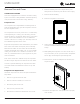
22. LIGHT ALL LED SEGMENTS
This will illuminate all the LEDs on the display to
ensure they work properly
23. ACTIVATE DEFROST /HARVEST
-Press and hold for 3 seconds to activate
24. FACTORY DEFAULTS
-Press and hold for 3 seconds to restore all values to
factory defaults
25. MAIN SOFTWARE
26. Does not apply to this model
27. FACTORY TEST MODEL
0 = O, 1 = On
28. COMPRESSOR RPM
29. FREEZE TIME ADJUST (MODEL 54 ONLY)
30. HARVEST TIME ADJUST (MODEL 54 ONLY)
31. LOW TEMP ALARM LIMIT (MODEL 55 ONLY)
32. HIGH TEMP ALARM LIMIT (MODEL 55 ONLY)
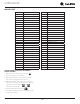
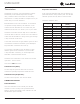
Display # Relay / Output
- Option #0 – Exit
- Option #1 – Relay 1
- Option #2 – Relay 2
- Option #3 – Relay 3
- Option #4 – Relay 4
- Option #5 – Relay 5
- Option #6 – Relay 6
- Option #7 – DC Output 1
- Option #8 – DC Output 2
- Option #9 – DC Output 3
- Option #10 – DC Output 4
- Option #11 – DC Output 5
- Option #12 – Serial output (Compressor)
SEE RELAY / OUTPUT CHART
41