USER GUIDE & SERVICE MANUAL Wine Refrigerators ● UCWC515 ● 15” Wine Refrigerator
USER GUIDE & SERVICE MANUAL u-line.
USER GUIDE u-line.com WELCOME TO U-LINE Congratulations on your U-Line purchase. Your product comes from a company with over five decades of premium modular ice making, refrigeration, and wine preservation experience. U-Line creates products focused on functionality, style, and inspired innovations — paying close attention to even the smallest details. Applications include residential, outdoor, ADA height compliant, marine, and commercial.
USER GUIDE u-line.com Safety and Warning NOTICE ! DANGER Please read all instructions before installing, operating, or servicing the appliance. Use this appliance for its intended purpose only and follow these general precautions with those listed throughout this guide: Service must be done by factory authorized service personnel. Any parts shall be replaced with like components. Failure to comply could increase the risk of possible ignition due to incorrect parts or improper service.
USER GUIDE u-line.com Disposal and Recycling ! DANGER RISK OF CHILD ENTRAPMENT. Before you throw away your old refrigerator or freezer, take off the doors and leave shelves in place so children may not easily climb inside. If the unit is being removed from service for disposal, check and obey all federal, state, and local regulations regarding the disposal and recycling of refrigeration appliances, and follow these steps completely: 1. Remove all consumable contents from the unit. 2.
USER GUIDE u-line.com Environmental Requirements This unit is designed to operate between 50°F (10°C) and 100°F (38°C). Higher ambient temperatures may reduce the unit’s ability to reach low temperatures and/or reduce ice production on applicable models. For best performance, keep the unit out of direct sunlight and away from heat generating equipment. In climates where high humidity and dew points are present, condensation may appear on outside surfaces. This is considered normal.
USER GUIDE u-line.com Electrical ! WARNING SHOCK HAZARD — Electrical Grounding Required. Never attempt to repair or perform maintenance on the unit until the electricity has been disconnected. Never remove the round grounding prong from the plug and never use a two-prong grounding adapter. Altering, cutting or removing power cord, removing power plug, or direct wiring can cause serious injury, fire, loss of property and/or life, and will void the warranty.
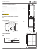
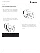
USER GUIDE u-line.com 14 15⁄16” (379 mm) Cutout & Product Dimensions PREPARE SITE Your U-Line product has been designed for either freestanding or built-in installation. When built-in, your unit FRONT does not require additional air space for top, sides, or 28” (711 mm) rear. However, the front grille must NOT be obstructed, 33 11⁄16” (855 mm) and clearance is required for an electrical connection in the rear. ! CAUTION Unit can NOT be installed behind a closed cabinet 3 ½” (89 mm) door.
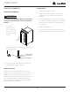
USER GUIDE u-line.com Anti-Tip Bracket 5. drawn for the outer edge. Mark spots for the screw FLOOR MOUNTED ANTI-TIP INSTALLATION 1. Locate two anti-tip brackets included with the kit. 2. Place the unit into the area where it will be installed. Place the anti-tip brackets on the floor against the line holes. Surrounding area (Top view) Check the door, sides, and top for a proper fit. Also test to make sure the door opens and closes freely. 3.
USER GUIDE u-line.com General Installation INSTALLATION LEVELING INFORMATION 1. Plug in the power/electrical cord. 2. Gently push the unit into position. Be careful not to entangle the cord or water and drain lines, if ! CAUTION applicable. To comply with applicable federal, state and local codes, this equipment may need to be caulked to 3. Re-check the leveling, from front to back and side to side. Make any necessary adjustments. The unit’s top the floor.
USER GUIDE u-line.com Grille Installation REMOVING AND INSTALLING GRILLE ! WARNING Disconnect electric power to the unit before removing the grille. When using the unit, the grille must be installed. ! WARNING DO NOT touch the condenser fins. The condenser fins are SHARP and can be easily damaged. Removing the grille 1. Disconnect power to the unit. 2. Loosen the two screws (1). 3. Remove grille (2) from unit. Installing the grille 1.
USER GUIDE u-line.com Door Swing Wall 2-1/8" Min. (54 mm) 90° Door Swing Units have a zero clearance for the door to open 90°, when installed adjacent to cabinets. Stainless Steel models require 2-1/8" (54 mm) door clearance to accommodate the handle if installed next to a wall.
USER GUIDE u-line.com Door Adjustments 5. Remove hinge pin from bottom hinge and install in left-hand bottom hinge. DOOR ALIGNMENT AND ADJUSTMENT Align and adjust the door if it is not level or not sealing properly. If the door is not sealed, the unit may not cool Bottom Left Hinge properly, or excessive frost or condensation may form in Bottom Right Hinge the interior. NOTICE Properly aligned, the door’s gasket should be firmly in contact with the cabinet all the way around the door (no gaps).
USER GUIDE u-line.com First Use Initial startup requires no adjustments. When plugged in, the unit will begin operating under the factory default settings. If the unit was turned off during installation, simply press and the unit will immediately switch on. To turn the unit off, press . NOTICE Temperature displayed reflects actual temperature inside unit. If the temperature displayed is different than selected, the unit is progressing towards the selected temperature.
USER GUIDE u-line.com Control Operation CONTROL FUNCTION GUIDE FUNCTION COMMAND NOTES ON/OFF Press Unit will immediately turn On or OFF and release When the display is flashing, press Adjust Temperature Press or and release or to adjust the set point temperature.
USER GUIDE u-line.com Airflow and Product Loading NOTICE Restricting airflow may result in poor product AIRFLOW performance, product failure, and uneven internal External temperatures and may freeze contents.
USER GUIDE u-line.com Interior Adjustments 5. Once removed, retract the slides. Note: The slides on the rack have a thin coating which All models feature side mounted rack supports with 19 is used to block moisture and provide lubrication. Use adjustment positions. care when handling. All Wine Refrigerator models ship with 5 racks designed to hold the maximum number of typical white and red Wine Rack Installation wine bottles. Remove and reposition racks as desired to 1.
USER GUIDE u-line.com Wine Storage Options WINE RACK BOTTLE POSITION Specially designed horizontal wine racks properly position the bottles so the wine remains in contact with the cork, which ensures the cork does not become dry.
USER GUIDE Cleaning CLEANING VS. SANITIZING u-line.com CLEAN INTERIOR COMPONENTS Use warm or hot water with dish soap to clean all removed This guide will address both the cleaning and the sanitizing components and interior surfaces. You may use a vinegar and of the unit. water solution in place of soap. Proceed to sanitizing.
USER GUIDE u-line.com INTERIOR CLEANING & SANITIZING Remove Wine Rack NOTICE 1. Fully extend empty rack 2. Firmly grasp both sides of rack and lift front end of Do not use any solvent-based or abrasive cleaners. These types of cleaners may transfer taste and/or odor to the interior products and damage or discolor the interior. Remove Slide-out Metal Shelf 1. Remove all items from shelf. 2. Pull shelf out far enough to firmly grasp both sides.
USER GUIDE 3. u-line.com 5. Remove evaporator cover. Remove 4 rack supports by removing 4 screws on each one. a. Remove thermistor cover - use a flat tool to pry out the push pin fastener Rack Supports Rack Supports b. Remove 8 screws (3 on each side 2 on top) 3-b 3-a 3-a 6. Remove screws and spacers from evaporator and carefully pull evaporator forward - just enough to be able to wipe both surfaces of the evaporator and the back wall. c.
USER GUIDE u-line.com Remove LED Light Cover Remove Door, Brackets, and Hinge 1. With a flat screwdriver, carefully pry LED light cover 1. Hold door to keep it from falling. from ceiling. LED light strip will hang down loosely. 2. Remove top hinge pin. 3. Remove door by tilting forward and lifting door off bottom hinge. Hinge Pin 4. 2. Take out screws and remove both hinges. Bracket Thoroughly clean and sanitize LED light cover Note: DO NOT clean the LED light strip.
USER GUIDE u-line.com DEFROSTING Under normal conditions this unit does not require manual defrosting. Minor frost on the rear wall or visible through the evaporator plate vents is normal and will melt during each cycle. If there is excessive build-up of 1/4” (6 mm) or more, manually defrost the unit. Ensure the door is closing and sealing properly. High ambient temperature and excessive humidity can also produce frost.
USER GUIDE u-line.com Cleaning Condenser INTERVAL - EVERY SIX MONTHS To maintain operational efficiency, keep the front grille free of dust and lint, and clean the condenser when necessary. Depending on environmental conditions, more or less frequent cleaning may be necessary. ! WARNING Disconnect electric power to the unit before cleaning the condenser. NOTICE DO NOT use any type of cleaner on the condenser unit. Condenser may be cleaned using a vacuum, soft brush, or compressed air. 1.
USER GUIDE u-line.com Extended Non-Use VACATION/HOLIDAY, PROLONGED SHUTDOWN The following steps are recommended for periods of extended non-use: 1. Remove all consumable content from the unit. 2. Disconnect the power cord from its outlet/socket and leave it disconnected until the unit is returned to service. 3. If ice is on the evaporator, allow ice to thaw naturally. 4. Clean and dry the interior of the unit. Ensure all water has been removed from the unit. 5.
USER GUIDE u-line.com Troubleshooting • Evaporator: Refrigerant flowing through an evaporator may sound like boiling liquid. BEFORE CALLING FOR SERVICE • Condenser Fan: Air moving through a condenser may be heard. • Automatic Defrost Drain Pan: Water may be heard dripping or running into the drain pan when the unit is in the defrost cycle. If you think your U-Line product is malfunctioning, read the CONTROL OPERATION section to clearly understand the function of the control.
USER GUIDE CHECKING PRODUCT TEMPERATURE u-line.com Causes which affect the internal temperatures of the cabinet include: • Temperature setting. • Ambient temperature where installed. • Installation in direct sunlight or near a heat source. • The number of door openings and the time the door is open. To check the actual product temperature in the unit: • The time the internal light is illuminated. (This mainly affects product on the top rack or shelf.) 1.
R/B Door switch L/T Door switch R/B Evap temp R/B Zone temp L/T Evap temp L/T Zone temp Condenser fan R/B Evap fan L/T Evap fan Blue light White light W 11 22 12 IFI An te n 1 1 Co nt ro 4 VC C cs 6 sti D iag no Programming na 1 l FUSE Open Open Open Open Open Open Black Open N.C. White 1 r Us e Wire Diagram fac e 1 10 5 In te r 42392_A Compressor White (Neutral) Black (Live) PLUG 220-240 VOLT 115 V (If Applicable) POWER CORD ASSEMBLY USER GUIDE u-line.
USER GUIDE u-line.com Product Liability Field service technicians are authorized to make an initial assessment in the event of reported damages. If there are any questions about the process involved, the technician should call U-Line for further explanation. While inspecting for defects or installation issues, photos should be taken to document any damages or issues found.
USER GUIDE Warranty Claims The following information defines the parameters for filing a warranty claim: Units must be registered prior to warranty submittal. Customers may register at www.U-Line.com. A proof of purchase is required. We also accept the following information to update warranty: • Valid serial number needed • Valid model number needed • Claims must be submitted online at www.U-LineService.com • u-line.
USER GUIDE u-line.
USER GUIDE u-line.com Ordering Replacement Parts Parts may be ordered online at www.U-Line.com See our contact information below: www.U-LineService.com (with service login) Phone Number: +1.800.779.2547 NOTICE Use only genuine U-Line replacement parts. The use of non-U-Line parts can reduce speed of ice production, cause water to overflow from ice maker mold, damage the unit, and void the warranty. Warranty parts will be shipped at no charge after U-Line confirms warranty status.
USER USER GUIDE GUIDE u-line.com u-line.com SAFETY • INSTALLATION & INTEGRATION • OPERATING INSTRUCTIONS • MAINTENANCE • SERVICE R-600A Specifications Gloves and Eye Protection must be used. For R-600a refrigerant service tips and more videos, go to: www.u-line.com/videos. ! WARNING Flammability warnings for a pure-iso-butane refrigerant. R-600a is considered non-toxic, but is flammable when mixed with air. Keep a dry powder type fire extinguisher in the work area.
USER USER GUIDE GUIDE u-line.com u-line.com SAFETY • INSTALLATION & INTEGRATION • OPERATING INSTRUCTIONS • MAINTENANCE • SERVICE ! WARNING Only skilled and well trained service technicians permitted to service R-600a equipped products. R-600A SPECIFICATIONS/LABELING R-600a equipped products are labeled (both the unit and the compressor). R-600a is colorless and odorless. All tools and equipment must be approved for use with R-600a refrigerant.
USER GUIDE GUIDE USER u-line.com u-line.com SAFETY • INSTALLATION & INTEGRATION • OPERATING INSTRUCTIONS • MAINTENANCE • SERVICE Evacuate/reclaim via the piecing pliers to ensure the When re-brazing, the system must be purged with dry system is empty of R-600a before any system work is nitrogen and at least one access point open to the performed. atmosphere. When re-brazing, proper ventilation is required along with constant monitoring for the presence of R600a refrigerant.
USER GUIDE GUIDE USER u-line.com u-line.com SAFETY • INSTALLATION & INTEGRATION • OPERATING INSTRUCTIONS • MAINTENANCE • SERVICE The low side of the refrigeration system (evaporator, Proper ventilation during service is required. compressor and suction line) must be leak tested with the compressor off (equalized pressure). Never apply a torch to a charged R-600a refrigeration system. RECHARGING No air is ever to be allowed inside the refrigeration system (R-600a refrigerant or dry nitrogen only).
USER GUIDE u-line.
USER GUIDE u-line.com Compressor Specifications FMXA9C REFRIGERANT R600A VOLTAGE 230 VAC FREQUENCY 43-134 Hz Electrocution can cause death or serious injury. START WINDING 20 Ohm at 77o F Burns from hot or cold surfaces can cause serious RUN WINDING 20 Ohm at 77o F injury. Take precautions when servicing this unit. RUN TO START 20 Ohm at 77o F LRA 1.7 A FLA 1.7 A STARTING DEVICE Inverter CF02C05 OVERLOAD Inverter CF02C05 ! DANGER Disconnect the power source.
USER GUIDE Troubleshooting - Extended ! CAUTION Never attempt to repair or perform maintenance on the unit until the main electrical power has been disconnected from the unit. u-line.com NORMAL OPERATING SOUNDS All models incorporate rigid foam insulated cabinets to provide high thermal efficiency and maximum sound reduction for its internal working components. Despite this technology, your model may make sounds that are unfamiliar.
USER GUIDE u-line.com TROUBLESHOOTING GUIDE Concern Potential Causes Action Not Cooling Compressor overheating Verify proper air flow through condenser. Is condenser clean? Confirm condenser fan operation. Frozen Product Frost Buildup Inside Unit Display Not Working Compressor not operating Test overload and relay, replace as needed. Compressor operating - no cooling Refer to System Diagnosis Guide. Control set too cold Adjust Set Point Temp accordingly.
USER GUIDE u-line.com MAIN CONTROL ! CAUTION The main control board is very robust and is rarely the cause of system issues. It is important to fully diagnose the board for any suspected failures before attempting to remove the board for replacement or service. Follow the guidelines below to fully test and diagnose the main control. Precautions must be taken while working with live electrical equipment. Be sure to follow proper safety procedures while performing tests on live systems.
USER GUIDE u-line.com Control Operation-Service CONTROL FUNCTION GUIDE UI BUTTON LAYOUT 1 1. 2 3 4 5 6 FUNCTION COMMAND ON/OFF Press Sabbath Mode See “Sabbath Mode” section DISPLAY/OPTIONS and release Unit will immediately turn ON or OFF Hidden Button -Access Service Menu SHOWROOM MODE -No LED directly above. All LEDs turn on with button environment. When in this mode the only functions will be This mode is designed to show units in a display the control and cabinet lights.
USER GUIDE u-line.com SERVICE MODE GUIDE SERVICE MODE GUIDE 0. Exit 1. Thermistor 1 temperature not including offsets. 2. Thermistor 2 temperature not including offsets. 3. Thermistor 3 temperature not including offsets. 4. Thermistor 4 temperature not including offsets. 5. Thermistor 1 offset. (+/- 10) 6. Thermistor 2 offset. (+/- 10) 7. Thermistor 3 offset. (+/- 10) 8. Thermistor 4 offset. (+/- 10) 9. Thermistor 2 set point 10. Thermistor 3 set point. 11. Thermistor 4 set point. 12.
USER GUIDE u-line.com E3: Thermistor 3 open. 25. E4: Thermistor 4 open (Does not apply to this model). 26. Does not apply to this model E5: Thermistor 1 shorted. 27. FACTORY TEST MODEL MAIN SOFTWARE E6: Thermistor 2 shorted. 0 = Off, 1 = On E7: Thermistor 3 shorted. 28. COMPRESSOR RPM E8: Thermistor 4 shorted (Does not apply to this 29. FREEZE TIME ADJUST (MODEL 54 ONLY) model). 30. HARVEST TIME ADJUST (MODEL 54 ONLY) E9: Door 2 (lower) open. 31.
USER GUIDE u-line.
Water Main Compressor Compressor Compressor Compressor Compressor Compressor Compressor Compressor Compressor Compressor Compressor Compressor Compressor Compressor Clear Ice, 3 Class **BV315-***1A **BV318-***1A **BV324-***1A **BV336-***1A **BV515-***1A **BV524-***1A **DR324-***1A **FZ324-***1A **RE315-***1A **RE318-***1A **RE324-***1A **RE336-***1A **RE515-***1A 01 03 04 06 07 09 13 15 17 19 20 22 23 Control Operation-Service 46 Compressor Compressor Compressor Compressor Compr
USER GUIDE u-line.com Thermistors Evaporator Thermistor Thermistors are used for various temperature readings. If the evaporator thermistor fails, the unit will rely on a Thermistors provide reliable temperature readings preset defrost timer during defrost cycles. The unit will USER GUIDE using a resistance which varies based on surrounding u-line.com otherwise operate normally. Refer to defrost section. temperatures.
USER GUIDE u-line.com Defrost This unit defrosts every 12 hours of compressor runtime for 45 minutes. If you have verified that the unit does not have an ambient air leak, utilize the Control Operation - Service section and adjust unit to defrost every 9 hours for 60 minutes. Also, adjust the #2 thermistor to -4 instead of 0.
USER GUIDE Remove Fan and Cover u-line.com 6. Remove insulating foam from refrigerant line passthrough hole as needed to gain clearance for fan plug. CONVECTION COOLING This unit is equipped with an advanced convection cooling system. Convection cooling stabilizes cabinet temperature, cools product faster and increases energy efficiency. 7. Remove internal shelving. 8. Remove 8 evaporator cover screws. 9.
USER GUIDE u-line.com NOTICE Fan must be oriented to pull air in through lower evaporator cover vents and push air out at fan mounting location. 13. Installation is the reverse of removal. 14. Care must be taken to assure the bottom of the evaporator cover is reinstalled behind the front edge of the train trough. 15. Use sealant gum to seal any openings at rear of unit before replacing rear cover. 16. Reinstall unit taking care to level, space and secure as found.
U-Line Corporation (U-Line) Limited Warranty One Year Limited Warranty For one year from the date of original purchase, this warranty covers all parts and labor to repair or replace any part of the product that proves to be defective in materials or workmanship. For products installed and used for normal residential use, material cosmetic defects are included in this warranty, with coverage limited to 60 days from the date of original purchase.