QUICK START GUIDE DISPENSERS • CDE224E (115v) • 4 Tap Mixed 30663_B
QUICK START GUIDE USER GUIDE u-line.com u-line.com WELCOME TO U-LINE Congratulations on your U-Line purchase. Your product comes from a company with over five decades of premium modular ice making, refrigeration, and wine preservation experience. U-Line creates products focused on functionality, style, and inspired innovations — paying close attention to even the smallest details. Applications include residential, outdoor, ADA height compliant, marine, and commercial.
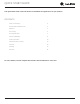
QUICK START GUIDE u-line.com This Quick Start Guide covers the basics of installation and general use of your product. CONTENTS Safety and Warning 4 Environmental Requirements 5 Electrical 5 Door Swing 5 Door Adjustments 6 General Installation 8 Control Operation 18 Airflow & Product Loading 18 First Use 18 Cleaning 20 Warranty 25 For more details, see the complete User Guide & Service Manual on u-line.com.
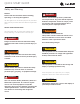
QUICKGUIDE START GUIDE USER u-line.com u-line.com Safety and Warning NOTICE ! DANGER Please read all instructions before installing, operating, or servicing the appliance. Service must be done by factory authorized service personnel. Any parts shall be replaced Use this appliance for its intended purpose only and follow with like components.
QUICK START GUIDE 16-1/2" 90° Door Swing Environmental Requirements 16-1/2" 90° Door Swing u-line.com NOTICE Stainless Black and White Models Electrical installation mustModels observe all state and local codes. This unit requires connection to a This model is intended for indoor/interior applications only 2115WC Models grounded (three-prong), polarized receptacle and is not to be used in installations that are open/ Wall Wall electrician.
QUICK START GUIDE u-line.com Door Adjustments REVERSING THE DOOR HINGE COVER Location of the unit may make it desirable to mount the door on the opposite side of the cabinet. Hinge cover included with the literature bag is optional. The hinge hardware will be removed and reinstalled on the opposite side of the cabinet. To install hinge cover: 1. Press hinge cover squarely over hinge.
QUICK START GUIDE 1. u-line.com Install top hinge and door: Remove door by tilting forward and lifting door off bottom hinge. Retain shoulder washers; they will be reused. 2. Use a Philips screwdriver to remove hinge pin and reinstall on the opposite surface of the hinge. 3. Remove three screws from hinge holes on the opposite side. Reinstall into holes where the hinge was removed. Take care not to scratch cabinet. Remove bottom hinge: 1. Remove bottom hinge from cabinet using a 1/4” socket. 1.
USER QUICKGUIDE START GUIDE u-line.com u-line.com General Installation The following components are shipped inside the unit: 1. Tap tower (handles, & hardware) 2. Nitrogen hoses (connecting hardware) 3. Infuser regulator (mounting hardware) 4. Liquid jumper line (with in-line filters) and gas jumper line 5. Lo-boy keg couplers 6. CO2 hoses (connecting hardware) 7. Cleaning solution (2-ounce packet) (Additional cleaner, ULACOFFEECLEAN, is available at u-line.com) 8.
USER GUIDE QUICK START GUIDE u-line.com u-line.com Connect Hoses to Tower 2. Your tower comes with two hoses already attached. 1. Install adapter plate to unit with 4 long screws and nuts (a) then place foam rubber gasket on top - open holes aligned (b). Attach gas jumper hose - line up and press in firmly. a b Note: The connector at the end of the gas jumper line is narrower to correspond with the connection in the tower. 2. 3. Insert all 4 hoses into the opening. 4.
USER QUICKGUIDE START GUIDE u-line.com u-line.com Install Tower on Countertop (See template on next page) Note: These instructions are designed for a standard 36" countertop application. Note: For a customized fit, it may be necessary to acquire screws that are sized to the thickness of your countertop. 1. Position refrigerator under countertop to determine the desired depth. 2. Use the dimensions from Diagram A to determine the center point of the tower mounting hole. 3.
QUICK START GUIDE USER GUIDE u-line.com u-line.com Template for Countertop Installation Note: Verify template has printed true to scale - double check hole dimensions and placement.
QUICK START GUIDE USER GUIDE u-line.com u-line.com Connecting Internal Nitrogen Source 4. Attach braided line to ball valve on tank regulator using white snap ring. 5. Attach other end of braided line to T- connector on infuser regulator. Install Infuser Regulator 1. Tap Tower Align infuser regulator To with pre-drilled holes in upper left/right of interior side wall. Use 2 screws to secure.
QUICK START GUIDE USER GUIDE u-line.com u-line.com Connecting External Nitrogen Source 4. Insert grommet into hole that corresponds to the drilled-out hole in bulkhead and apply food grade lubricant to inside of the grommet. 5. Inside cabinet push nitrogen hose through drilled-out hole. Note: Connection to an external Nitrogen source requires drilling one hole through the preinstalled bulkhead located near the top of the back wall. This will allow a grommet sized to .453" hose to fit.
QUICK START GUIDE USER GUIDE u-line.com u-line.com Connect Nitrogen to Kegs 1. Cut 2" of hose from supplied 1/4" white nitrogen hose. 2. Insert one end of hose into elbow on infuser regulator. 3. Attach T-connector to other end of hose. 4. Connect gas line from the tower to end of T-connector. 5. Connect blue gas line to center of T-connector. 7.
QUICKGUIDE START GUIDE USER u-line.com u-line.com Connecting External CO2 Source 5. Inside cabinet push CO2 hose through drilled-out hole. Note: Connection to an external CO2 source requires drilling a hole through the pre-installed bulkhead located near the top of the back wall. It is crucial to proper operation of the refrigerator Inside that air tight insulation is installed around the incoming CO2 hose. 6. Re-install back panel. Prepare bulkhead and back panel 1.
USER GUIDE QUICK START GUIDE u-line.com u-line.com Connecting Kegs to Tower 1. 4. Press down and rotate clockwise an additional 1/4 turn. Attach black coupler of the liquid jumper line to ball-tap keg. With your thumb press down on the top of the coupler while pulling up on the collar. Press coupler down firmly onto "out" valve. Release collar listen for a click. Pull up on the coupler to ensure it is locked down. 1/4 turn Out Valve 2.
QUICK START GUIDE USER GUIDE u-line.com u-line.com Connections When complete, the connections should look like this: To CO2 Source Two CO2 Lines 1/6 Slim Barrel To Nitrogen Source 1/4 Slim Barrel One Nitrogen Line Infuser Regulator Standard Ball-tap Keg Filter Assembly Standard infuser regulator setup One CO2 line and Two Nitrogen lines Alternate infuser regulator setup Two CO2 lines and One Nitrogen line LEVELING INFORMATION 1. ! CAUTION Use a level to confirm the unit is level.
QUICK START GUIDE u-line.com Control Operation CONTROL FUNCTION GUIDE FUNCTION COMMAND NOTES ON/OFF Press Unit will turn On or OFF Adjust Temperature Press or Toggle between ºF / ºC Hold and and hold for 5 seconds When the display is flashing, press and release or for 5 seconds The display will change units Airflow and Product Loading First Use Initial startup requires no adjustments. If the unit was AIRFLOW turned off, press and hold for 5 seconds to turn unit on.
QUICK START GUIDE u-line.com Setting CO2 Pressure To minimize foam for most beverages the pressure should be set between 8-12 PSI. • Set the pressure by turning the handle on the front of the regulator counterclockwise until it is all the way out. This will turn the regulator off. • Turn the valves on the bottom of the regulator to the side to ensure no CO2 will pass through the regulator (Diagram A). • Pull the pin on the sides of the couplers to release built up pressure from the kegs.
USER GUIDE QUICK START GUIDE u-line.com u-line.com Cleaning CLEAN INTERIOR COMPONENTS CLEANING VS. SANITIZING Use warm or hot water with dish soap to clean all removed This guide will address both the cleaning and the sanitizing components and interior surfaces. You may use a vinegar and of the unit. water solution in place of soap. Proceed to sanitizing.
QUICK START GUIDE USER GUIDE u-line.com u-line.com INTERIOR CLEANING & SANITIZING Tap Heads NOTICE Clean the tap heads with warm soapy water. Remove nose Do not use any solvent-based or abrasive cones and soak in the cleaning solution for at least five cleaners. These types of cleaners may transfer taste minutes. Rinse with clean potable water, dry and reattach. and/or odor to the interior products and damage or discolor the interior.
QUICK START GUIDE USER GUIDE u-line.com u-line.com Cleaning the Beer-Dispensing System Clean the system using a suitable solution designed for beerdispensing systems. Beer cleaning kits are also available. Solution and/or kit not included. 1. Close CO2 tank. 2. Pull pin on coupler to release pressure from keg. 3. Remove tap coupler from keg. 4. Remove CO2 line from tap coupler. 5. Open tap coupler to allow cleaning solution to flow through it: • Push base of coupler inward and rotate clockwise.
QUICK START GUIDE USER GUIDE 9. u-line.com u-line.com Remove tap head from tower with supplied tap head wrench. Disassemble, and place all the parts in drainage bucket. 10. Add washer and attach cleaning pump connector to tower. Tighten with tap head wrench. 11. Pump all the solution through the beverage line. 12. Allow tap coupler and tap head to soak in drainage bucket and then use tap head brush to clean tap head. 13. Rinse out and refill plastic jar with clean water.
QUICK START GUIDE USER GUIDE u-line.com u-line.com DEFROSTING Under normal conditions this unit does not require manual defrosting. Minor frost on the rear wall or visible through the evaporator plate vents is normal and will melt during each cycle. If there is excessive build-up of 1/4” (6 mm) or more, manually defrost the unit. Ensure the door is closing and sealing properly. High ambient temperature and excessive humidity can also produce frost.
U-Line Corporation (U-Line) Limited Warranty One Year Limited Warranty For one year from the date of original purchase, this warranty covers all parts and labor to repair or replace any part of the product that proves to be defective in materials or workmanship. For products installed and used for normal residential use, material cosmetic defects are included in this warranty, with coverage limited to 60 days from the date of original purchase.