USER GUIDE & SERVICE MANUAL SAFETY • INSTALLATION & INTEGRATION • OPERATING INSTRUCTIONS • MAINTENANCE • SERVICE RIGHT PRODUCT. RIGHT PLACE. RIGHT TEMPERATURE. SINCE 1962.
USER GUIDE u-line.
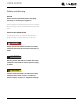
USER GUIDE u-line.com WELCOME TO U-LINE Congratulations on your U-Line purchase. Your product comes from a company with over five decades of premium modular ice making, refrigeration, and wine preservation experience. U-Line continues to be the American leader, delivering versatility and flexibility for multiple applications including residential, light commercial, outdoor and marine use.
USER GUIDE u-line.com SAFETY • INSTALLATION & INTEGRATION • OPERATING INSTRUCTIONS • MAINTENANCE • SERVICE Safety and Warning NOTICE Please read all instructions before installing, operating, or servicing the appliance.
USER GUIDE u-line.com SAFETY • INSTALLATION & INTEGRATION • OPERATING INSTRUCTIONS • MAINTENANCE • SERVICE Disposal and Recycling ! DANGER RISK OF CHILD ENTRAPMENT. Before you throw away your old refrigerator or freezer, take off the doors and leave shelves in place so children may not easily climb inside.
USER GUIDE u-line.com SAFETY • INSTALLATION & INTEGRATION • OPERATING INSTRUCTIONS • MAINTENANCE • SERVICE Environmental Requirements This model is intended for indoor/interior applications only and is not to be used in installations that are open/ exposed to natural elements. This unit is designed to operate between 50°F (10°C) and 100°F (38°C). Higher ambient temperatures may reduce the unit’s ability to reach low temperatures and/or reduce ice production on applicable models.
USER GUIDE u-line.com SAFETY • INSTALLATION & INTEGRATION • OPERATING INSTRUCTIONS • MAINTENANCE • SERVICE Electrical ! WARNING SHOCK HAZARD — Electrical Grounding Required. Never attempt to repair or perform maintenance on the unit until the electricity has been disconnected. Never remove the round grounding prong from the plug and never use a two-prong grounding adapter.
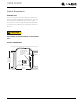
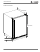
USER GUIDE u-line.com SAFETY • INSTALLATION & INTEGRATION • OPERATING INSTRUCTIONS • MAINTENANCE • SERVICE Cutout Dimensions PREPARE SITE Your U-Line product has been designed for either freestanding or built-in installation. When built-in, your unit does not require additional air space for top, sides, or rear. However, the front grille must NOT be obstructed, and clearance is required for an electrical connection in the rear. ! CAUTION Unit can NOT be installed behind a closed cabinet door.
USER GUIDE u-line.
USER GUIDE u-line.com SAFETY • INSTALLATION & INTEGRATION • OPERATING INSTRUCTIONS • MAINTENANCE • SERVICE Side-by-Side Installation Two units may be installed side-by-side. Cutout width for a side-by-side installation is the cutout dimension of a single unit times two. No trim kit is required. However, 1/4" (6 mm) of space 3. Place bracket over holes and attach to unit with two screws removed in step 2 using a T-25 Torx driver. Tighten screws fully. 4. Gently push units into position.
USER GUIDE u-line.com SAFETY • INSTALLATION & INTEGRATION • OPERATING INSTRUCTIONS • MAINTENANCE • SERVICE Water Hookup PREPARE PLUMBING ! CAUTION The water valve uses a standard 1/4" (6.35 mm) Do not use any plastic water supply line. The line compression fitting. U-Line recommends using accessory is under pressure at all times. Plastic may crack water hook up kit – part # WATERHOOKUP.
USER GUIDE u-line.com SAFETY • INSTALLATION & INTEGRATION • OPERATING INSTRUCTIONS • MAINTENANCE • SERVICE 9. Install retaining clip. 3. Locate water valve inlet. 4. Break away filler feature in bushing with flat screwdriver. Remove ZLWK ɠDW screwdriver 5. Thread water line through back panel hole (with bushing). 6. Locate water valve inlet and connect to valve. 7. Turn on water supply and check for leaks. 8. Reinstall back panel.
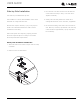
USER GUIDE u-line.com SAFETY • INSTALLATION & INTEGRATION • OPERATING INSTRUCTIONS • MAINTENANCE • SERVICE Anti-Tip Bracket 1. Slide unit out so screws on top of unit are easily accessible. 2. Remove the two screws from the opposite side of the hinge assembly using a T-25 Torx driver (see below). NOTE: 1224 models shown with four screw. 1215 models only have three screws, but same screws are used in both applications. 3.
USER GUIDE u-line.com SAFETY • INSTALLATION & INTEGRATION • OPERATING INSTRUCTIONS • MAINTENANCE • SERVICE General Installation INSTALLATION 1. Plug in the power/electrical cord. LEVELING INFORMATION 1. Use a level to 2. Gently push the unit into position. Be careful not to confirm the unit is kink the water supply line or entangle the cord. level. Level should be placed along top 3. Re-check the leveling, from front to back and side to edge and side edge side. Make any necessary adjustments.
USER GUIDE u-line.com SAFETY • INSTALLATION & INTEGRATION • OPERATING INSTRUCTIONS • MAINTENANCE • SERVICE Grille - Plinth Installation REMOVING AND INSTALLING GRILLE ! WARNING Disconnect electric power to the unit before removing the grille. When using the unit, the grille (plinth strip/base fascia) must be installed. ! WARNING DO NOT touch the condenser fins. The condenser fins are SHARP and can be easily damaged. Removing the grille 1. Disconnect power to the unit. 2. Loosen the two screws (1).
USER GUIDE u-line.com SAFETY • INSTALLATION & INTEGRATION • OPERATING INSTRUCTIONS • MAINTENANCE • SERVICE Door Swing Wall Wall 1/4" Min. (6 mm) 90 Door Swing 2-1/8" Min. (54 mm) 90 Door Swing Units have a zero clearance for the door to open 90°, when installed adjacent to cabinets. Stainless Steel and black and white models require 2-1/8" (54 mm) door clearance to accommodate the handle if installed next to a wall. Integrated models require 1/4" (6 mm) clearance if installed next to a wall.
USER GUIDE u-line.com SAFETY • INSTALLATION & INTEGRATION • OPERATING INSTRUCTIONS • MAINTENANCE • SERVICE Door Stop 3. On 24" models, a second pin is included for the bottom hinge. Repeat steps above for second hinge. Your U-Line unit was shipped to you with the optional 90° pin(s). (Models that are 15" wide include 1 pin. Models that are 24" wide include 2 pins.) The unit’s door will open NOTE: Threaded pin will be inserted from the bottom. freely without a fixed opening angle limitation.
USER GUIDE u-line.com SAFETY • INSTALLATION & INTEGRATION • OPERATING INSTRUCTIONS • MAINTENANCE • SERVICE Door Adjustments DOOR ALIGNMENT AND ADJUSTMENT Align and adjust the door if it is not level or is not sealing properly. If the door is not sealed, the unit may not cool properly, or excessive frost may form in the interior. NOTICE Properly aligned, the door’s gasket should be firmly in contact with the cabinet all the way around the door (no gaps).
USER GUIDE u-line.com SAFETY • INSTALLATION & INTEGRATION • OPERATING INSTRUCTIONS • MAINTENANCE • SERVICE 3. Remove door by tilting forward and lifting door off 3. Rotate gasket 180°, aligning notch with magnet bottom hinge. Retain shoulder washers; they will be assembly and pressing firmly into the gasket channel reused. starting at the corners. 4. Remove four screws from hinge holes on the opposite 4. Rotate door 180° to reverse. side. Reinstall into holes where the hinge was removed.
USER GUIDE u-line.com SAFETY • INSTALLATION & INTEGRATION • OPERATING INSTRUCTIONS • MAINTENANCE • SERVICE Free Standing Kit The free standing kit is an optional accessory. It is only used when unit is not installed in surrounding cabinetry. To install the kit: 1. Remove grille (see GRILLE-PLINTH INSTALLATION section). 3. Align front hole with hole in shell accessory, hole in base, and hole in grille. Tighten screw. 2.
USER GUIDE u-line.com SAFETY • INSTALLATION & INTEGRATION • OPERATING INSTRUCTIONS • MAINTENANCE • SERVICE First Use All U-Line controls are preset at the factory. Initial startup requires no adjustments. NOTICE U-Line recommends allowing the unit to run overnight before loading with product. U-Line recommends discarding the ice produced during the first two to three hours of operation to avoid possible dirt or scale that may dislodge from the water line.
USER GUIDE u-line.com SAFETY • INSTALLATION & INTEGRATION • OPERATING INSTRUCTIONS • MAINTENANCE • SERVICE Control Operation Up Down Not Light Power Used LED CONTROL FUNCTION GUIDE FUNCTION COMMAND DISPLAY/OPTIONS ON/OFF Press and release Unit will immediately turn ON or OFF.
USER GUIDE u-line.com SAFETY • INSTALLATION & INTEGRATION • OPERATING INSTRUCTIONS • MAINTENANCE • SERVICE Ice ! CAUTION ICE MAKER OPERATION When the ice bucket is full, the ice making mechanism will NEVER use an ice pick, knife or other sharp shut off. However, the refrigeration system will continue instrument to separate cubes. Shake the ice to cool and maintain the ice supply. bucket instead.
USER GUIDE u-line.com SAFETY • INSTALLATION & INTEGRATION • OPERATING INSTRUCTIONS • MAINTENANCE • SERVICE 3. Turn the adjusting screw toward the minus (-) sign ICE MAKER ADJUSTMENT (clockwise) for smaller cubes or toward the plus (+) Ice Cube Thickness Adjustment sign (counterclockwise) for larger cubes. Interval - As Required On ice maker equipped models, adjust the cube size by changing water amount injected into the ice maker 4. Install the ice maker assembly cover.
USER GUIDE u-line.com SAFETY • INSTALLATION & INTEGRATION • OPERATING INSTRUCTIONS • MAINTENANCE • SERVICE L Sabbath Mode 1 2 3 4 5 6 7 This unit is Star-K certified and offers a Sabbath mode. Sabbath mode disables system responses to user initiated activities and all external functions, including lighting, display and audible alarms. The unit will still maintain internal temperatures and set points. View a full list of Star-K certified U-Line units at www.star-k.org. To enable Sabbath Mode: 1.
USER GUIDE u-line.com SAFETY • INSTALLATION & INTEGRATION • OPERATING INSTRUCTIONS • MAINTENANCE • SERVICE Airflow and Product Loading NOTICE The unit requires proper airflow to perform at its highest efficiency. Do not block the front grille, or the unit will not perform as expected. Do not install the unit behind a door. When loading your unit, leave space between the evaporator and product loaded. Anything in direct contact with the evaporator is subject to freezing.
USER GUIDE u-line.com SAFETY • INSTALLATION & INTEGRATION • OPERATING INSTRUCTIONS • MAINTENANCE • SERVICE Interior Shelves NOTICE REMOVING AND INSTALLING INTERIOR SHELVES Make sure the shelves are inserted fully into the unit. The edge strip toward the rear prevents cans and bottles from freezing against the cold evaporator. 3 1 2 For models equipped with glass shelves having recessed shelf supports, remove the shelves as follows: 1.
USER GUIDE u-line.com SAFETY • INSTALLATION & INTEGRATION • OPERATING INSTRUCTIONS • MAINTENANCE • SERVICE Cleaning If any surface discoloring or rusting appears, clean it EXTERIOR CLEANING and a nonabrasive cloth. Always clean with the grain. Vinyl Clad (Black or White) Always finish with Claire® Stainless Steel Polish and Clean surfaces with a mild detergent and warm water solution. Do not use solvent-based or abrasive cleaners.
USER GUIDE u-line.com SAFETY • INSTALLATION & INTEGRATION • OPERATING INSTRUCTIONS • MAINTENANCE • SERVICE High ambient temperature and excessive humidity can also produce frost. ! CAUTION DO NOT use an ice pick or other sharp instrument to help speed up defrosting. These instruments can puncture the inner lining or damage the cooling unit. DO NOT use any type of heater to defrost. Using a heater to speed up defrosting can cause personal injury and damage to the inner lining.
USER GUIDE u-line.com SAFETY • INSTALLATION & INTEGRATION • OPERATING INSTRUCTIONS • MAINTENANCE • SERVICE Cleaning Condenser INTERVAL - EVERY SIX MONTHS To maintain operational efficiency, keep the front grille free of dust and lint, and clean the condenser when necessary. Depending on environmental conditions, more or less frequent cleaning may be necessary. ! WARNING Disconnect electric power to the unit before cleaning the condenser. ! WARNING DO NOT touch the condenser fins.
USER GUIDE u-line.com SAFETY • INSTALLATION & INTEGRATION • OPERATING INSTRUCTIONS • MAINTENANCE • SERVICE Extended Non-Use VACATION/HOLIDAY, PROLONGED SHUTDOWN For questions regarding winterization, please The following steps are recommended for periods of call U-Line at +1.800.779.2547. extended non-use: 1. Remove all consumable content from the unit. 2. Disconnect the power cord from its outlet/socket and leave it disconnected until the unit is returned to service.
USER GUIDE u-line.com SAFETY • INSTALLATION & INTEGRATION • OPERATING INSTRUCTIONS • MAINTENANCE • SERVICE Troubleshooting • Evaporator: Refrigerant flowing through an evaporator may sound like boiling liquid. BEFORE CALLING FOR SERVICE If you think your U-Line product is malfunctioning, read the CONTROL OPERATION section to clearly understand the function of the control.
USER GUIDE u-line.com SAFETY • INSTALLATION & INTEGRATION • OPERATING INSTRUCTIONS • MAINTENANCE • SERVICE Problem Possible Cause and Remedy Digital Display Shows 1-16 or 99 A factory test mode may be enabled. Adjust the temperature to 99 and press the light icon. Product Is Freezing. Because product in contact with the rear wall may freeze, ensure no product is touching the rear wall. Adjust the temperature to a warmer set point. Product Is Not Cold Enough.
USER GUIDE u-line.com SAFETY • INSTALLATION & INTEGRATION • OPERATING INSTRUCTIONS • MAINTENANCE • SERVICE U-Line Corporation (U-Line) Limited Warranty One Year Limited Warranty For one year from the date of original purchase, this U-Line product warranty covers all parts and labor to repair or replace any part of the product that proves to be defective in materials or workmanship.
CAP L/T LIGHT EVAP FAN COND FAN TEST TERMINAL REFRIG TEMP EVAP TEMP FZR TEMP IM TEMP DOOR SWITCH EMBRACO COMPRESSOR 8 1 5 6 10 1 16 9 J9 J10 TE AN A NN G OG FUSE 10 1 OPEN Y PR CONTROL BOARD RA M GROUND: GREEN or GREEN W/ YELLOW IN TO RELAY LA SP DI NEUTRAL WHITE HOT GAS VALVE ORANGE HOT TO COMPRESSOR WHITE WHITE 6 4 5 3 2 1 3 1 6 4 BLACK (HOT) (GROUND) GREEN W/ YELLOW WHITE (NEUTRAL) GREEN W/YELLOW WHITE PURPLE RED BLACK/YELLOW LIGHT BLUE WHITE WATE
USER GUIDE u-line.com SAFETY • INSTALLATION & INTEGRATION • OPERATING INSTRUCTIONS • MAINTENANCE • SERVICE Product Liability Field service technicians are authorized to make an initial assessment in the event of reported damages. If there are any questions about the process involved, the technician should call U-Line for further explanation. While inspecting for defects or installation issues, photos should be taken to document any damages or issues found.
USER GUIDE u-line.com SAFETY • INSTALLATION & INTEGRATION • OPERATING INSTRUCTIONS • MAINTENANCE • SERVICE Warranty Claims warranty status. We also accept the following information to verify warranty status: The following information defines the parameters for filing a warranty claim: • New Construction Occupancy Documents • Valid serial number needed • Valid model number needed • Narda (or equivalent) form or submitted online at www.u-line.
Parts 25 8 29 18 1 U-CO1224FS-00B Item 22 35 14 36 17 40 28 15 16 12 2 27 19 21 24 30 26 23 20 34 38 13 7 11 6 5 4 9 Description U-Line P/N 1 Anti tip bracket w/screws 80-54239-00 2 Back panel 80-54204-00 3 Compression nut/sleeve 80-54355-00 4 Compressor electricals only 80-54300-00 5 Compressor w/electricals 80-54299-00 6 Condenser assembly 80-54301-00 7 Condenser fan w/screws 80-54014-00 8 Display module 80-54236-00 9 Door assembly w/hinges 80-54315-0
USER GUIDE u-line.com SAFETY • INSTALLATION & INTEGRATION • OPERATING INSTRUCTIONS • MAINTENANCE • SERVICE Ordering Replacement Parts If you have a purchasing account, please utilize our service website to order parts. Orders may also be placed by Fax or phone. See our contact information below: www.U-LineService.com (with service login) FAX Number: +1.414.354.5696 Phone Number: +1.800.779.2547 NOTICE Use only genuine U-Line replacement parts.
USER GUIDE u-line.
USER GUIDE u-line.com SAFETY • INSTALLATION & INTEGRATION • OPERATING INSTRUCTIONS • MAINTENANCE • SERVICE Compressor Specifications OVERLOAD PROTECTOR STARTING RELAY ! DANGER C S Electrocution can cause death or serious injury. R Burns from hot or cold surfaces can cause serious injury. Take precautions when servicing RELAY COVER CAPACITOR this unit. ULIN_0368_A Disconnect the power source.
USER GUIDE u-line.
USER GUIDE u-line.
USER GUIDE u-line.com SAFETY • INSTALLATION & INTEGRATION • OPERATING INSTRUCTIONS • MAINTENANCE • SERVICE NOTICE Check Voltage At Wall Outlet No Voltage Alert Customer Of Power Failure Frequently toggling the compressor relay could force the compressor into overload. The compressor will automatically deactivate during Voltage an overload and will remain deactivated until the Verify Voltage At Main Control Voltage Input No Voltage Replace Power Cord overload switch cools.
USER GUIDE u-line.com SAFETY • INSTALLATION & INTEGRATION • OPERATING INSTRUCTIONS • MAINTENANCE • SERVICE THERMISTOR FAILURE Zone Thermistor If the zone thermistor fails, the unit will continue to operate in a timed limp mode for 10 minutes on and 45 minutes off. The unit will otherwise operate normally. The error will be displayed in the error log. Evaporator Thermistor If the evaporator thermistor fails, the unit will rely on a preset defrost time during defrost cycles.
USER GUIDE u-line.com SAFETY • INSTALLATION & INTEGRATION • OPERATING INSTRUCTIONS • MAINTENANCE • SERVICE Control Operation - Service UI BUTTON LAYOUT 1 2 3 4 5 6 7 1. Hidden Button -Accesses Service Menu -No LED directly above. All LEDs turn on with button activation except #7. 2. Up Button -Increases temperature -Navigates through service menu -LED activated with button activation. 3. Down Button -Decreases temperature -Navigates through service menu -LED activated with button activation 4.
USER GUIDE u-line.com SAFETY • INSTALLATION & INTEGRATION • OPERATING INSTRUCTIONS • MAINTENANCE • SERVICE CONTROL FUNCTION QUICK GUIDE FUNCTION COMMAND DISPLAY/OPTIONS ON/OFF Press and release Unit will immediately turn ON or OFF Press and release to leave interior light Glass door wine captains and beverage centers Toggle lights Adjust refrigerator temperature on for 3 hours only.
USER GUIDE u-line.com SAFETY • INSTALLATION & INTEGRATION • OPERATING INSTRUCTIONS • MAINTENANCE • SERVICE SERVICE MODE GUIDE # Service Mode Menu Item 2. THERMISTOR 2 — EVAPORATOR This shows the pure thermistor reading with no offsets taken into account. 1 View thermistor #1 (no offsets) 2 View thermistor #2 (no offsets) 3 View thermistor #3 (no offsets) 4 View thermistor #4 (no offsets) 5 Adjust thermistor #1 offset 6 Adjust thermistor #2 offset 4.
USER GUIDE u-line.com SAFETY • INSTALLATION & INTEGRATION • OPERATING INSTRUCTIONS • MAINTENANCE • SERVICE 13. ADJUST DEFROST DURATION — 0 TO 99 MINUTES The length of the defrost can be adjusted 0 to 99 minutes long. The other defrost parameters still apply. Lengthening a defrost may cause higher than normal temperatures in the refrigerator section. 14. VIEW ERROR LOG A list of the errors in the order they occurred will scroll once on the display. All errors are logged in memory.
USER GUIDE u-line.com SAFETY • INSTALLATION & INTEGRATION • OPERATING INSTRUCTIONS • MAINTENANCE • SERVICE 27. SOFTWARE VERSION — USER INTERFACE Displays software version of the user interface. 28. LOG IN PERIOD Factory use only - do not adjust. 29. FACTORY TEST MODE Should be 0. 0.
N/A N/A 2260ZWC N/A 2245WC 2260WC N/A 2245RDC N/A N/A 2245R 2260RDC N/A 2224ZWC N/A N/A 2224WC N/A N/A 2224RGL 2260R N/A 2224R 2260DC N/A N/A 2218RGL N/A N/A 2218R 2224BEV Ice Maker 2 CO1224F 2218WC N/A CLR1215 1224RSOD N/A N/A 1224RF N/A N/A 1224R ADA24R N/A 1224DWR 1224WC N/A Mullion Heater N/A N/A N/A N/A N/A Hot Gas Valve Hot Gas Valve Hot Gas Valve N/A N/A N/A N/A N/A N/A N/A N/A Ice Maker 1 Pump N/A N/A N/A N/A N/A N/A N/A N/A
USER GUIDE u-line.com SAFETY • INSTALLATION & INTEGRATION • OPERATING INSTRUCTIONS • MAINTENANCE • SERVICE Thermistors 1000 Series Self Preservation Mode: Thermistors are used for various temperature readings. minutes. The unit will cycle on for 10 minutes then off for 40 Thermistors provide reliable temperature readings using a resistance which varies based on surrounding temperatures. If a faulty thermistor is suspected it may be tested using an accurate ohmmeter.
USER GUIDE u-line.com SAFETY • INSTALLATION & INTEGRATION • OPERATING INSTRUCTIONS • MAINTENANCE • SERVICE Defrost The models below have automatic or frost free design and do not require manual defrosting under normal conditions.
USER GUIDE u-line.com SAFETY • INSTALLATION & INTEGRATION • OPERATING INSTRUCTIONS • MAINTENANCE • SERVICE Remove Fan and Cover 4. Unplug fan connection. PARTS REPLACEMENT 5. Remove two nuts holding the fan to the fan bracket. Note: These models do not require removal of the ice maker or freezer housing to access the fan motor, drain or evaporator. 6. Replace with new fan making sure air flows in at top and out at bottom. REPLACING EVAPORATOR FAN MOTOR 1. Disconnect unit from power source. 7.
USER GUIDE u-line.com SAFETY • INSTALLATION & INTEGRATION • OPERATING INSTRUCTIONS • MAINTENANCE • SERVICE Replace Ice Maker 5. Remove three screws from wall of freezer housing. The new ice maker assembly you have received will have 6. Remove ice maker assembly. a plug-in connection. INSTALL ICE MAKER REMOVE ICE MAKER 1. Use three screws to mount new ice maker assembly to wall of freezer housing. 1. Unplug the unit. 2. Reconnect plug.