
User Guide & Service Manual


USER GUIDE
Troubleshooting - Extended 3
u-line.com
SAFETY • INSTALLATION & INTEGRATION • OPERATING INSTRUCTIONS • MAINTENANCE • SERVICE
MAIN CONTROL
The main control board is very robust and is rarely the
cause of system issues. It is important to fully diagnose
the board for any suspected failures before attempting to
remove the board for replacement or service. Follow the
guidelines below to fully test and diagnose the main
control.
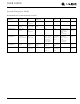
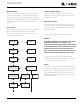
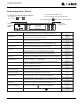
Power Fault
If the unit does not (or seems to not) power on, follow the
flow chart below to help diagnose the issue. Before
beginning it is important to first verify the unit is not
simply set to sabbath mode.
Testing The Main Control
If the main control is suspected of being faulty, the
following procedure should be performed to verify main
control for functionality.
Relay & DC Outputs
One of the primary functions of the main control is to
operate the multiple relay and DC outputs during each
cycle. Verify proper operation of these relays using the
following procedure.
1. Enter “Relay Toggle” through the service menu.
NOTICE
Frequently toggling the compressor relay could
force the compressor into overload. The
compressor will automatically deactivate during
an overload and will remain deactivated until the
overload switch cools. This could take some
time. It is important to allow the compressor at
least 5 minutes off time between relay cycles.
2. Toggle the relay. Its related component should
activate / deactivate with the switching of the relay. If
it does not, see “Component Testing.”
Inputs
The main control monitors a number of thermistor inputs
and switch states during operation. It would be unlikely
that an error in reading an input would be at the board
level. Always attempt to replace the faulty switch or
thermistor input with a known working sample to verify
proper board operation.
Check Voltage
At Wall Outlet
Verify Voltage
At Main Control
Voltage Input
Check Fuse F1
For Continuity
Open Door.
Is the UI Now
Functional?
Replace Main
Board
Replace Reed
Switch.
Replace
Fuse
Replace
Power Cord
Alert Customer
Of Power Failure
Is the Reed
Switch Operating
Properly?
Is the door open? The
Display will not activate
while the door is closed
Inspect Customer UI
and Data Cable
Connect Test Display
To J5.
Cycle Power And
Check For Operation
No Voltage
No Voltage
Voltage
Continuity
Operating
Not Operating
No Continuity
No
No
No
Yes
Yes
Yes
Voltage