USER GUIDE SAFETY • INSTALLATION & INTEGRATION • OPERATING INSTRUCTIONS • MAINTENANCE • SERVICE RIGHT PRODUCT. RIGHT PLACE. RIGHT TEMPERATURE. SINCE 1962.
USER GUIDE u-line.
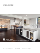
USER GUIDE u-line.com WELCOME TO U-LINE Congratulations on your U-Line purchase. Your product comes from a company with over five decades and three generations of premium modular ice making, refrigeration, and wine preservation experience. U-Line continues to be the American leader, delivering versatility and flexibility for multiple applications including residential, light commercial, outdoor and marine use.
USER GUIDE u-line.com SAFETY • INSTALLATION & INTEGRATION • OPERATING INSTRUCTIONS • MAINTENANCE • SERVICE Safety and Warning ! DANGER NOTICE This unit contains R600a (Isobutane) which is a Please read all instructions before installing, flammable hydrocarbon. It is safe for regular operating, or servicing the appliance. use. Do not use sharp objects to expedite defrosting.
USER GUIDE u-line.com SAFETY • INSTALLATION & INTEGRATION • OPERATING INSTRUCTIONS • MAINTENANCE • SERVICE Disposal and Recycling ! DANGER RISK OF CHILD ENTRAPMENT. Before you throw away your old refrigerator or freezer, take off the doors and leave shelves in place so children may not easily climb inside.
USER GUIDE u-line.com SAFETY • INSTALLATION & INTEGRATION • OPERATING INSTRUCTIONS • MAINTENANCE • SERVICE Environmental Requirements This model is intended for indoor/interior applications only and is not to be used in installations that are open/ exposed to natural elements. This unit is designed to operate between 50°F (10°C) and 100°F (38°C). Higher ambient temperatures may reduce the unit’s ability to reach low temperatures and/or reduce ice production on applicable models.
USER GUIDE u-line.com SAFETY • INSTALLATION & INTEGRATION • OPERATING INSTRUCTIONS • MAINTENANCE • SERVICE Electrical ! WARNING SHOCK HAZARD — Electrical Grounding Required. Never attempt to repair or perform maintenance on the unit until the electricity has been disconnected. Never remove the round grounding prong from the plug and never use a two-prong grounding adapter.
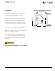
USER GUIDE u-line.com SAFETY • INSTALLATION & INTEGRATION • OPERATING INSTRUCTIONS • MAINTENANCE • SERVICE Cutout Dimensions CUTOUT DIMENSIONS PREPARE SITE Your U-Line product has been designed exclusively for a built-in installation. When built-in, your unit does not Preferred location for electrical outlet is in adjacent 5/8" cabinet. (16 mm) require additional air space for top, sides, or rear. However, the front grille must NOT be obstructed.
USER GUIDE u-line.
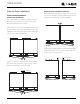
USER GUIDE u-line.com SAFETY • INSTALLATION & INTEGRATION • OPERATING INSTRUCTIONS • MAINTENANCE • SERVICE Side-by-Side Installation OTHER SITE REQUIREMENTS Side-by-Side Installation Hinge-by-Hinge Installation (Mullion) When installing two units hinge-by-hinge, 13/16" (22 mm) is required for integrated models. Additional space may be needed for any knobs, pulls or handles installed.
USER GUIDE u-line.com SAFETY • INSTALLATION & INTEGRATION • OPERATING INSTRUCTIONS • MAINTENANCE • SERVICE Anti-Tip Bracket SIDE MOUNT Left Hinged Cabinet Right Hinged Cabinet ! CAUTION The anti-tip bracket must be installed to prevent the unit from tipping when doors are fully opened or excess weight is placed on the front of the unit. The anti-tip bracket has multiple mounting options. Mounting will depend on your particular cabinet configuration. Locate 3 #8x5/8" screws included with your unit.
USER GUIDE u-line.com SAFETY • INSTALLATION & INTEGRATION • OPERATING INSTRUCTIONS • MAINTENANCE • SERVICE General Installation 1. Plug in the power/electrical cord. 1. Use a level to confirm the unit is level. Level 2. Gently push the unit into position. Be careful not to should be placed along top edge and side edge INSTALLATION 1 entangle the cord. as shown. 3. Re-check the leveling, from front to back and side to side. Make any necessary adjustments.
USER GUIDE u-line.com SAFETY • INSTALLATION & INTEGRATION • OPERATING INSTRUCTIONS • MAINTENANCE • SERVICE Integrated Panel Dimensions Metric measurements rounded and optimized. STANDARD PANELS NOTICE When applying an integrated panel to a unit, ensure that both sides are finished in order to prevent warping. NOTICE Due to differences in surrounding cabinetry the Standard Panel Dimensions panel may not perfectly align with drawer.
USER GUIDE u-line.com SAFETY • INSTALLATION & INTEGRATION • OPERATING INSTRUCTIONS • MAINTENANCE • SERVICE HANDLELESS INTEGRATED DRAWER PANELS 3. Prepare the insert(s) that will back up the handleless The following procedure is designed to provide a finished, design. Wooden Insert – Cut 1/8" thick wooden handleless solid panel for a 24" (600 mm) drawer that insert(s) to the dimensions below. seamlessly integrates with its surrounding cabinetry. Prepare two panels for your drawer unit.
USER GUIDE u-line.com SAFETY • INSTALLATION & INTEGRATION • OPERATING INSTRUCTIONS • MAINTENANCE • SERVICE Handleless Integrated Panel Dimensions 1/8" (3 mm) Top Design 1/4" (6 mm) 7/8" (22 mm) Ref.
USER GUIDE u-line.com SAFETY • INSTALLATION & INTEGRATION • OPERATING INSTRUCTIONS • MAINTENANCE • SERVICE EXTENDED INTEGRATED PANELS NOTICE Due to differences in surrounding cabinetry the panel may not perfectly align with drawer. The procedure below is designed to provide a finished panel that seamlessly integrates with surrounding cabinetry.
USER GUIDE u-line.com SAFETY • INSTALLATION & INTEGRATION • OPERATING INSTRUCTIONS • MAINTENANCE • SERVICE Front Side Integrated Panel/Integrated Frame Integrated Panel U-Line Unit Cabinet U-Line Unit 3-5/16" (89 mm) to 4-5/16" (114 mm) > 3-5/16" (> 89 mm) 3-5/16" (89 mm) to 4-5/16" (114 mm) Floor Front Side Extended Integrated Panel/Extended Integrated Frame U-Line Unit Cabinet * Panel can extend beyond the drawer.
USER GUIDE u-line.
USER GUIDE u-line.com SAFETY • INSTALLATION & INTEGRATION • OPERATING INSTRUCTIONS • MAINTENANCE • SERVICE INTEGRATED GRILLE (PLINTH STRIP/BASE FASCIA) DIMENSIONS 3-5/16" to 4-5/16" (84 mm to 110 mm) Integrated Grille - Plinth Dimensions PREPARE AND INSTALL INTEGRATED GRILLE (PLINTH STRIP/BASE FASCIA) panel. Recommended panel thickness is between 1/4" (6 mm) and 3/8" (9 mm). Height will vary from 3-5/16" 1" (25 mm) shape your integrated grille (plinth strip/base fascia) 1-9/16" (40 mm) 1.
USER GUIDE u-line.com SAFETY • INSTALLATION & INTEGRATION • OPERATING INSTRUCTIONS • MAINTENANCE • SERVICE Integrated Panel Installation 1. Fully open drawer. 6. Using a Phillips screwdriver, place one screw into each of the 6 pilot holes and screw down. Do not overtighten screws. 2. Align top of panel with top edge of drawer. Center panel on drawer. Integrated Panel NOTICE Integrated Panel Due to differences in floor construction or surrounding cabinetry, the panel may not sit 7.
USER GUIDE u-line.com SAFETY • INSTALLATION & INTEGRATION • OPERATING INSTRUCTIONS • MAINTENANCE • SERVICE Grille - Plinth Installation Installing the grille (plinth strip/base fascia) REMOVING AND INSTALLING GRILLE (PLINTH STRIP/BASE FASCIA) 1. Align slots in grille (plinth strip/base fascia) rail with ! WARNING Disconnect electrical current to the unit before removing the grille (plinth strip/base fascia). When using the unit, the grille (plinth strip/base fascia) must be installed.
USER GUIDE u-line.com SAFETY • INSTALLATION & INTEGRATION • OPERATING INSTRUCTIONS • MAINTENANCE • SERVICE Drawers CHECKING DRAWER ALIGNMENT The unit’s drawers are aligned at the factory before shipment. However, their alignment could have been disturbed during shipment or during overlay panel installation. Check each drawer to confirm that it is DRAWER REMOVAL 1. Confirm that the unit is unplugged from wall outlet. 2. Unplug the drawer’s connection wiring (top drawer only). aligned: 3.
USER GUIDE u-line.com SAFETY • INSTALLATION & INTEGRATION • OPERATING INSTRUCTIONS • MAINTENANCE • SERVICE SIDE-TO-SIDE ADJUSTMENT FRONT-TO-BACK ADJUSTMENT The drawer will need a Side- The drawer will need a Front- to-Side Adjustment if, when to-Back Adjustment if, when viewed from the top, the viewed from the side, the drawer front is not square with drawer front is cocked the sides of the cabinet. This Not Aligned Side-to-Side on the unit’s liner. forward or back.
USER GUIDE u-line.com SAFETY • INSTALLATION & INTEGRATION • OPERATING INSTRUCTIONS • MAINTENANCE • SERVICE Minor Adjustment: Note: The mounting holes on the slide are slightly larger Severe Adjustment: Note: The slides have extra Mark and Drill New Mounting Holes mounting holes that may be used. than the screws’ diameter. 1. Loosen one slide’s mounting screws. 1. Loosen one slide’s rear Loosen Mounting Screws mounting screws. 2. Push the slide upward or Level the Slide 2.
USER GUIDE u-line.com SAFETY • INSTALLATION & INTEGRATION • OPERATING INSTRUCTIONS • MAINTENANCE • SERVICE RE-INSTALLATION OF DRAWER ! CAUTION Use care when handling the drawer. Drawer edges, drawer rail and the unit’s slide may be sharp. 1. Set the drawer’s rails onto the slides. 2. Re-install the rails’ mounting screws. 3. Plug in the drawer’s connection wiring (top drawer only).
USER GUIDE u-line.com SAFETY • INSTALLATION & INTEGRATION • OPERATING INSTRUCTIONS • MAINTENANCE • SERVICE First Use All U-Line controls are preset at the factory. Initial startup requires no adjustments. NOTICE U-Line recommends allowing the unit to run overnight before loading with product. When plugged in, the unit will begin operating under the factory default setting. Follow the on screen prompt for language selection and temperature units.
USER GUIDE u-line.com SAFETY • INSTALLATION & INTEGRATION • OPERATING INSTRUCTIONS • MAINTENANCE • SERVICE Control Operation Your unit is equipped with two zones. Each zone can be set to a different mode. Up Zone Indicator Zone Toggle Zone Indicator Select Deli 36°F Down Root 5O°F Can be displayed in Celsius Power U-Select Lighting CONTROL FUNCTION GUIDE FUNCTION COMMAND DISPLAY/OPTIONS OFF Press and hold Display will count down from 5 to off.
USER GUIDE u-line.
USER GUIDE u-line.com SAFETY • INSTALLATION & INTEGRATION • OPERATING INSTRUCTIONS • MAINTENANCE • SERVICE The following table lists modes which include the quick INTERIOR LIGHTING chill feature and the time which quick chill will run. Your U-Line 3000 Series unit uses a state of the art LED lighting system. Mode Run Time Beverage/Drinks 4 Hours Market/Fresh 4 Hours Root 1 Hour Pantry 4 Hours Deli 5 Hours To initiate quick chill: 1. Press to select the desired zone, left or right.
USER GUIDE u-line.com SAFETY • INSTALLATION & INTEGRATION • OPERATING INSTRUCTIONS • MAINTENANCE • SERVICE 3000 SERIES - CUSTOMER MENU ERROR NOTIFICATION The 3000 model series continuously monitors a series of Up Select inputs and parameters to ensure proper and efficient operation of your unit. Should the system detect a fault, WELCOME TO THE CUSTOMER MENU. USE UP/DOWN ARROWS TO SCROLL SETTINGS. an error notification will be displayed on the user interface. See below for a list of errors.
USER GUIDE u-line.com SAFETY • INSTALLATION & INTEGRATION • OPERATING INSTRUCTIONS • MAINTENANCE • SERVICE Languages Energy Saver Mode Up Energy Saver Mode Indicator DELI 36° F Up Select Select RETURN TO MENU LANGUAGES ENGLISH ROOT 50° F Can be displayed in Celsius Down Down Energy Saver mode reduces overall energy consumption by altering user set point, differential, lighting and tone settings.
USER GUIDE u-line.com SAFETY • INSTALLATION & INTEGRATION • OPERATING INSTRUCTIONS • MAINTENANCE • SERVICE 2. Press . The current setting will begin to flash. To access Factory Default: 1. Press 3. Press or to select a different level. 2. Press 4. Press to select “Factory Default”. . to confirm your choice. To restore settings to their factory default: Fahrenheit/Celsius 3. Press to select “Restore?” and press . Up Select 4. “Restore?” will change to “Restoring...
USER GUIDE u-line.com SAFETY • INSTALLATION & INTEGRATION • OPERATING INSTRUCTIONS • MAINTENANCE • SERVICE L Sabbath Mode 7. Press or to change “Off” to “On”. 8. Press to confirm your selection. The Display will fade out as the unit enters Sabbath Mode. Up Select RETURN TO MENU SABBATH MODE OFF? Sabbath Mode remains active until is quickly pressed and released. Down This unit offers a Sabbath mode for users who require this functionality during Sabbaths.
USER GUIDE u-line.com SAFETY • INSTALLATION & INTEGRATION • OPERATING INSTRUCTIONS • MAINTENANCE • SERVICE Airflow and Product Loading NOTICE The unit requires proper airflow to perform at its highest efficiency. Do not block the front grille, or the unit will not perform as expected. Do not install the unit behind a door. When loading your unit, leave space between the evaporator and product loaded. Anything in direct contact with the evaporator is subject to freezing.
USER GUIDE u-line.com SAFETY • INSTALLATION & INTEGRATION • OPERATING INSTRUCTIONS • MAINTENANCE • SERVICE Cleaning Integrated Models To clean integrated panels, use household cleaner per the EXTERIOR CLEANING cabinet manufacturer’s recommendation. Stainless Models Stainless door panels and handles can discolor when exposed to chlorine gas, pool chemicals, saltwater or cleaners with bleach.
USER GUIDE u-line.com SAFETY • INSTALLATION & INTEGRATION • OPERATING INSTRUCTIONS • MAINTENANCE • SERVICE NOTICE The drain pan was not designed to capture the water created when manually defrosting. To prevent water from overflowing the drain pan and possibly damaging water sensitive flooring, the unit must be removed from cabinetry. To defrost: 1. Disconnect power to the unit. 2. Remove all products from the interior. 3. Prop the door in an open position (2 in. [50 mm] minimum). 4.
USER GUIDE u-line.com SAFETY • INSTALLATION & INTEGRATION • OPERATING INSTRUCTIONS • MAINTENANCE • SERVICE Cleaning Condenser INTERVAL - EVERY SIX MONTHS To maintain operational efficiency, keep the front grille (plinth strip/base fascia) free of dust and lint, and clean the condenser when necessary. Depending on environmental conditions, more or less frequent cleaning may be necessary. ! WARNING Disconnect electric current to the unit before cleaning the condenser.
USER GUIDE u-line.com SAFETY • INSTALLATION & INTEGRATION • OPERATING INSTRUCTIONS • MAINTENANCE • SERVICE Extended Non-Use VACATION/HOLIDAY, PROLONGED SHUTDOWN The following steps are recommended for periods of extended non-use: 1. Remove all consumable content from the unit. 2. Disconnect the power cord from its outlet/socket and leave it disconnected until the unit is returned to service. 3. If ice is on the evaporator, allow ice to thaw naturally. 4. Clean and dry the interior of the unit.
USER GUIDE u-line.com SAFETY • INSTALLATION & INTEGRATION • OPERATING INSTRUCTIONS • MAINTENANCE • SERVICE Troubleshooting • Evaporator: Refrigerant flowing through an evaporator may sound like boiling liquid. BEFORE CALLING FOR SERVICE If you think your U-Line product is malfunctioning, read the CONTROL OPERATION section to clearly understand the function of the control.
USER GUIDE u-line.com SAFETY • INSTALLATION & INTEGRATION • OPERATING INSTRUCTIONS • MAINTENANCE • SERVICE Problem Possible Cause and Remedy Product is Not Cold Enough. Air temperature does not indicate product temperature. See CHECKING PRODUCT TEMPERATURE below. Adjust the temperature to a cooler set point. Ensure unit is not located in excessive ambient temperatures or in direct sunlight. Ensure the door is closing and sealing properly. Ensure the interior light has not remained on too long.
USER GUIDE u-line.com SAFETY • INSTALLATION & INTEGRATION • OPERATING INSTRUCTIONS • MAINTENANCE • SERVICE U-Line Corporation | Limited Warranty 1. U-Line Corporation (“U-Line”) warrants each U-Line product to be free from defects in materials and workmanship for a period of one year (two years on Modular 3000 Series) from the date of installation.
USER GUIDE u-line.com SAFETY • INSTALLATION & INTEGRATION • OPERATING INSTRUCTIONS • MAINTENANCE • SERVICE defective parts be returned, at your expense, to ULine’s factory in Milwaukee, Wisconsin, for inspection. Any action by you for breach of warranty must be commenced within one year after the applicable warranty period. 8.