
Use & Care Manual


CLR2160, CLRCO2175 23
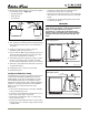
9. After unit is in its final position, finish routing drain
tube to the desired location. Common installations use
a floor drain, standpipe, garbage disposal, or Y-branch
tailpiece type drain connection (see
Figures 37, 38 and
39
).
10. Check to ensure unit is level both side to side and front
to back.
See Leveling on Page 14.
IMPORTANTIMPORTANT
For the gravity/floor drain or the standpipe be sure
to secure the drain line to these items to prevent it
from coming loose and causing water damage.
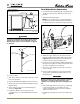
IMPORTANTIMPORTANT
For disposer or Y-branch tailpiece connections press
the drain tube over the barbed end of the connector
and secure with a worm clamp. Make sure the
knockout inside the tailpiece has been removed for
both types of connections. Depending on the size of
the Y-branch or disposer fitting, an adapter may be
necessary to interface between the 5/8” hose and
connection.
11. Turn the unit to the on position by holding the power
key for 10 seconds.
12. Pour 1 gallon of water into the ice bin and check all
connections for leaks. Ensure the water is flowing from
the bin. If the water does not flow from the bin there
may be an issue with the drain connection, such as kinks
or improper slope. If your unit has a drain pump, an
indicator of P1 on the display will alert you of a slow or
clogged drain.
13. If any issues are found, retrace the drain connection,
correct the issue and retest with water.
14. Go on to
8 Prepare Power Supply
.
Electrical Specifications
CAUTION
Electrical installation must observe all state and
local codes. This unit requires connection to a
grounded (three-prong), polarized receptacle that
has been placed by a qualified electrician.
The unit requires a grounded and polarized 115 VAC,
60 Hz, 15A power supply (normal household current).
An individual, properly grounded branch circuit or circuit
breaker is recommended. GFCI (ground fault circuit
interrupter) is usually not required for fixed location
appliances and is not recommended for your unit because
a GFCI could be prone to nuisance tripping. However, be
sure to consult your local codes.
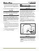
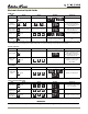
See Figure 42 for recommended receptacle location.
Plugging the unit into a receptacle located behind an
adjacent cabinet will allow the CLRCO2175 to be more
easily serviced with self-diagnostics without disturbing
your installation.
Figure 42
WARNING
SHOCK HAZARD — Electrical Grounding Required.
• Never remove the round grounding prong from
the plug and never use a two-prong grounding
adapter.
• Never use an extension cord to connect power to
the unit.
8 Prepare Power Supply
Acceptable
Location
Preferred
Location
for Receptacle
1-1/2"
7"
24"
ULIN_30096_5-7-07.fm Page 23 Friday, May 11, 2007 11:06 AM