
Specifications
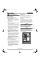

20 CLR2160, CLRCO2175
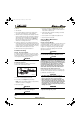
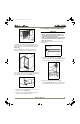
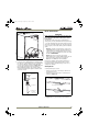
If using a Gravity Drain:
1. Slide 2 hose clamps onto the drain connection on the
rear of the appliance.
2. Insert the barbed fitting halfway into this connection.
3. On the other end of this barbed fitting attach the 5/8”
braided tubing.
4. Slide a clamp on each side of the barbed fitting as
shown
(see Figure 34).
5. Insulate the drain line, if necessary to prevent
condensation. Go on to Final Water/Drain Connection
Page 22.
Figure 33
Figure 34
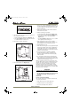
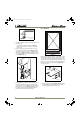
Factory-Installed Drain Pump
If your drain line will run up to a stand pipe, disposal
assembly or spigot assembly or does not otherwise meet
the requirements for a Gravity Drain, you may have
ordered the CLR2160 or CLRCO2175 with a U-Line P60
Drain Pump. See Figures 37, 38 and 39 for typical
installations requiring a Drain Pump. If you need to install
a P60 Drain Pump into your unit, see Locally-Installed
Drain Pump on Page 21.
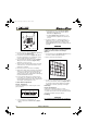
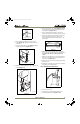
IMPORTANTIMPORTANT
Before installing your U-Line CLR2160 or CLRCO2175
with Factory-Installed U-Line P60 Pump, it is
extremely important to check and test all hose
connections at the drain pump. There is a possibility
that hose connections may have loosened during
shipment.
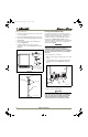
To check and test hose connections:
1. Make certain the unit is not plugged into an electrical
outlet.
2. Carefully push the power cord grommet through the
hole in the back panel (see
Figure 35
, CLRCO2175
shown).
Figure 35
3. Remove 12 screws and back panel.
WARNING
Back panel serves as a guard. DO NOT put your
hands inside the ice maker cabinet or attempt to
touch any components except the discharge tube
during testing. Failure to follow this warning
could result in serious personal injury or death.
Waste
Waste
Cold
Water
Shut-Off
Valve
Hot
Water
Gravity Drain
ULIN_0570_A
Drain Fitting from
Back of Unit
Worm Clamps
Drain Line
5/8" x 5/8"
Barb Connector
ULIN_S_0166b2_A
Power
Cord
Grommet
Drain
Fitting
Back
Panel
Water
Connection
Screws
ULIN_0574_A
ULIN_30096_5-7-07.fm Page 20 Friday, May 11, 2007 11:06 AM