
Specifications
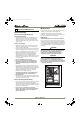

18 CLR2160, CLRCO2175
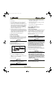
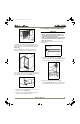
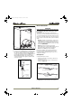
To install the door shelf:
1. Holding shelf in center, align notches (Figure 28, 1) in
shelf with bosses (Figure 28, 2) in door.
2. Tilt shelf at a 15°-20° angle and slide onto bosses at the
desired location.
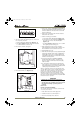
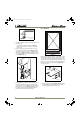
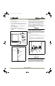
Glass Shelf Removal/Installation
Figure 29
1. Pull shelf out about 6" (Figure 29, 1) until back of
shelf clears the "hump" on the right-hand side.
2. Tilt right-hand edge of shelf up.
3. Remove shelf from unit by pulling out
(Figure 29, 2)
.
Insert the shelves as follows:
1. To move to a different position in the unit, insert shelf
at an angle, approximately 15-20°, over the rib in the
side of the unit where you want to place the shelf. The
shelf must be started into the unit at an angle to clear
the door.
2. Continue to slide the shelf into the unit at an angle
until it clears the door.
3. Lower the shelf and push it in completely.
CAUTION
Plumbing installation must observe all state and
local codes. All water and drain connections MUST
BE made by a licensed/qualified plumbing
contractor. Failure to follow recommendations and
instructions may result in damage and/or harm.
Water Supply Connection
When connecting the water supply, follow these
guidelines:
• Review the local plumbing codes before you install the
unit.
• Connect to the cold water supply.
• The water pressure should be between 20 and 120 psi.
• The water line MUST have a shut-off valve in the 1/4”
O.D. supply line.
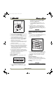
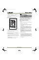
• Leave approximately 8’ of water line to be coiled
behind the appliance (see Figure 30). The water line
should be looped into 2 coils. This will allow the unit to
be removed for cleaning and servicing. However, make
certain that the tubing is not pinched or damaged
during installation.
NOTE: U-Line requires the use of copper tubing
for installation. Do not use any plastic water supply
line because the line is under pressure at all times.
Plastic may crack or rupture with age and cause water
damage to your home.
To connect to water supply:
1. Locate the desired cold water supply location. Attach a
1/4” copper line to this location and route the tubing
to the appliance. Leave approximately 8’ of water line
to be coiled behind the appliance. The water line
should be looped into 2 coils. This will allow the line to
flex when removing the unit for cleaning and servicing
(see Figure 30).
ULIN_0276_A
1
2
7 Prepare Plumbing
ULIN_30096_5-7-07.fm Page 18 Friday, May 11, 2007 11:06 AM