
Installation guide

www.U-LineService.com 14 05/2007
CLR2160/CLRCO2175 Ice Makers
Checking Door Alignment
The unit’s door is aligned at the factory before shipment.
However, its alignment could have been disturbed during
shipment or during door panel installation.
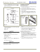
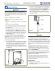
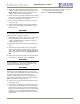
IMPORTANT
Properly aligned, the door should be 1/8" below the top of
the unit’s cabinet, NOT flush with the top (see
Figure 31
).
1. Compare the top edge of the door to the top edge of
the cabinet.
2. If the door edge is 1/8" below and parallel to the top of
the cabinet, go on to
6 Prepare Plumbing
. If it is not,
note whether the side opposite the hinge needs to be
moved UP or DOWN, and use the following procedure.
Note: If door is adjusted correctly, but panel is not square
with the adjacent cabinets, slight adjustments can be
made by drilling the holes in the vinyl coated steel panel
slightly oversized. See Figure 25 on Page 12.
Adjusting Door Alignment
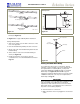
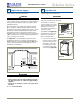
1. Remove top hinge screw
pin (Phillips screwdriver,
see Figure 32). Remove
door by tilting forward
and lifting off bottom
hinge pin.
2. With door upside-down,
loosen but do not remove
the two screws on the
door’s bottom hinge plate.
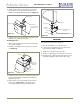
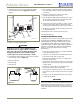
3. See
Figure 33
. If the top far edge of the door needs to
move UP, move the hinge plate toward the outside of
the door and retighten screws. If the top far edge of the
door needs to move DOWN, move the hinge plate
toward the inside of the door and retighten screws.
4. Mount the door to recheck alignment and repeat Steps
2 and 3 if further adjustment is necessary.
5. When top edge of door is parallel to top edge of
cabinet, remove the door and ensure the two screws
are secure.
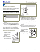
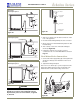
6. Remove the door closers from the bottom hinge, clean
thoroughly and lubricate the mating surfaces with
petroleum jelly.
7. Reinstall the closers, lining
up the bosses with holes in
hinge and hinge plate (see
Figure 34
).
8. Mount the door, install top
hinge pivot pin and go on
to
6 Prepare Plumbing
.
5 Adjust Door
1/8"
Figure 31
ULIN_0133_A
Figure 32
Notch
Slotted
Mounting
Holes
Raise
Outside
Door Edge
Lower
Outside
Door Edge
Figure 33
Figure 34
Door
Closer
Inserts
Boss