
User Guide

CLR2060 — Clear Ice Maker
02/2005 11 www.U-LineService.com
™
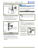
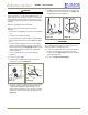
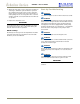
3. Install the pivot post into the new Replacement Bottom
Hinge (using the 7/64" hex key or Phillips screwdriver)
and install the hinge onto the unit.
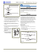
4. Replace the door closure assembly onto the bottom
pivot post (see
Figure 25
). Be sure that bosses on
closers align with holes in hinge and hinge plate.
IMPORTANT
Pivot posts must be cleaned. Closers must also be clean
and greased to ensure proper operation.
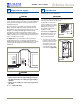
5. Place the modified door onto the pivot post.
6. Position door and install the pivot post into the top
hinge (using the 7/64" hex key or Phillips screwdriver).
7. Adjust door as needed for proper closure. Go on to
5
Adjust Door
.
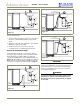
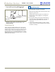
Checking Door Alignment
The unit’s door is aligned at the factory before shipment.
However, its alignment could have been disturbed during
shipment or during door panel installation.
IMPORTANT
Properly aligned, the door should be 1/8" below the top of
the unit’s cabinet, NOT flush with the top (see
Figure 26
).
1. Compare the top edge of the door to the top edge of
the cabinet.
2. If the door edge is 1/8" below and parallel to the top of
the cabinet, go on to
6 Prepare Plumbing
. If it is not,
note whether the side opposite the hinge needs to be
moved UP or DOWN, and use the following procedure.
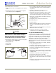
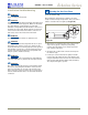
Adjusting Door Alignment
1. Remove top hinge screw
pin (7/64
"
Allen wrench or
Phillips screwdriver,
depending on your unit’s
construction, see Figure
27). Remove door by
tilting forward and lifting
off bottom hinge pin.
2. With door upside-down,
loosen but do not remove
the two screws on the
door’s bottom hinge plate.
Top Pivot Plate
Door Panel
Wood Panel Top Hinge Plate
(5/8" Longer than Existing Top Hinge Plate)
#8-32
x
1/2"
Flat Head Screw
Three Places
Pivot Post
Figure 24
Wood Panel Bottom Hinge Plate
(5/8" Longer than Existing Bottom Hinge Plate)
#8-32
x
1/2" Flat Head Screw
Three Places
Door Closure Top
Door Closure Bottom
Pivot Post
Boss
Boss
Existing
Door
Figure 25
5 Adjust Door
1/8"
Figure 26
Figure 27