® INSTALL GUIDE 2000 SERIES DRAWER MODELS REFRIGERATORS COMBO® REFRIGERATOR/FREEZER/ICE MAKERS WINE CAPTAIN® MODELS 2275DWRCS C2275DWROL 2275DWRCOL C2275DWRS The Built-In Undercounter Leader Since 1962 2275DWRW U-LINE.
1 Table of Contents Safety Precautions Safety Alert Definitions.........................................................................................................................................1 General Precautions ..............................................................................................................................................1 Inspect & Plan Product Registration ..............................................................................................................
2 Safety Precautions General Precautions IMPORTANT • PLEASE READ all instructions before installing, operating, or servicing the appliance. • Proper installation procedures must be followed when completing an installation or relocation of a unit. Consult the installation guide before any installation begins. U-Line contact information appears on the rear cover of this guide.
Tools / Material Required 3 Inspect & Plan • Screwdrivers — slotted and Phillips head (If installing a 3/4” Full Overlay panel) • 3/4” overlay frame material • Cutting Tools Product Registration • Drill & Drill Bits You have received a carton containing your U-Line Combo Drawer Model Ice Maker/Refrigerator or U-Line Refrigerator with a package inside containing a Use and Care Guide, a Product Registration Card, water connection parts and Anti-Tip Kit.
4 Prepare Site Your U-Line product has been designed for either free-standing or built-in installation. When built-in, your unit does not require additional air space for top, sides, or rear. However, the front grille must NOT be obstructed and clearance is required for an electrical connection in the rear. C2275DWR Series IMPORTANT • Unit can NOT be installed behind a closed cabinet door. 24" WARNING 34-1/4" to 35-1/8" 7" SHOCK HAZARD — Electrical Grounding Required.
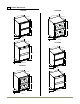
C2275DWR & 2275DWRC 5 Product Dimensions 2275DWRW 2275DWRC 23-15/16” 24" 23-1/4" 23-1/4” 33-7/8” 33-7/8” 3-7/8” 3-7/8” Black Overlay 24" 23-3/8” C2275DWR 24" 23-1/4" 33-7/8" 33-7/8” 3-7/8” Stainless Steel 2275DWRW 3-7/8” Black 24" 23-15/16” 23-3/8” 23-3/8” 33-7/8" 33-7/16” 3-7/8” 3-7/8” Stainless Steel Stainless Product Dimensions 4
Other Site Requirements 6 Clearance Information Power Supply The unit must be installed in a wall or under a counter-top to allow for the installation of the Anti-Tip Kit (see Page 14). WARNING The unit requires a grounded and polarized 115 VAC, 60 Hz, 15A circuit (normal household current). See Electrical Specifications. Water Supply The Anti-Tip Kit must be installed on this unit before it is used. Never use the drawers as steps or as a shelf to support more than the drawers’ contents.
7 Standard Drawers IMPORTANT Checking Drawer Alignment The unit’s drawers are aligned at the factory before shipment. However, their alignment could have been disturbed during shipment or during overlay panel installation. Check each drawer to confirm that it is aligned: Aligned Front-to-Back Aligned Side-to-Side Drawer adjustments are made by moving the slide that carries the drawer’s rail.
Minor Adjustment: Minor Adjustment: Screws Should Be Loose Note: The mounting holes on the slide are slightly larger than the screws’ diameter. Note: The mounting holes on the slide are slightly larger than the screws’ diameter. 1. Loosen one slide’s mounting screws. 1. Loosen one slide’s mounting screws. 2. Level the slide. 3. Retighten the screws. See Figure 18. Level the Slide Mounting Screws 2. Push the slide upward or downward to match the position of the other slide. 3. Retighten the screws.
Full Overlay Drawer Panels 8 Drawer Panel Installation Drawer Panel Preparation Custom 1/4" Drawer Panel Inserts Full overlay drawer panels completely cover the drawer fronts and handles to give a built-in appearance. Overlay units are shipped ready for Full Overlay installation. Drawer Panel Preparation Custom drawer panels can be inserted into the drawer fronts.
Attaching the Full Overlay Panel CAUTION 1. If user-supplied cabinet handles will be used, attach their hardware to the overlay panel at this time. IMPORTANT User-supplied cabinet handles MUST be counter bored to make sure mounting hardware is below surface of overlay panel. Failure to do so can cause damage to overlay panel and/or drawer. Overlay panel will not sit flush to drawer if mounting hardware is not counter bored.
You may also mount your overlay to your grille using hook and loop type fasteners. U-Line recommends using 3M® Dual lock® fasteners. To mount your overlay using a hook and loop fastener follow the instructions below. 9 Wood Grille Overlay Grille Overlay Your models grille is designed to accept a wood grille overlay. An overlay may be used to compliment a door overlay and provides a seamless look for your surrounding decor. Follow the instructions below to prepare and install your grille overlay.
1/4 1/2 3-3/32 2-1/8 11/64 U-Line Grill Overlay Installation 23-7/8 19-5/8 22-7/8 5/16 8-1/2 10-5/16 Grille Overlay Dimensions 24 Inch Models FULL R 1/2 5/16 TYP 2X 1/2 TYP 3X (7/16 ) Grille Drawing 11
10 Prepare Plumbing 10 Level The Unit Leveling Information CAUTION Plumbing installation must observe all state and local codes. All water and drain connections MUST BE made by a licensed/qualified plumbing contractor. Failure to follow recommendations and instructions may result in damage and/or harm. Water Supply Connection When connecting the water supply, follow these guidelines: • Review the local plumbing codes before you install the unit. • Connect to the cold water supply.
2. Insert the screws through the anti-tip bracket (B) and attach the bracket to the unit. Tighten screws securely. 11 Install Unit 3. Repeat for the other side. 1. Plug in the power cord. 2. Open the top drawer and press the POWER icon to turn the unit OFF. Note: The bracket should be flush with the surface it is being attached to. If it is not, loosen the screws and slide the bracket against the mounting surface. Tighten screws securely. 3.
First Time Start Up All U-line units are shipped from the factory with controls that are preset. No initial adjustments are required. Once installation and leveling is complete, the unit is ready for initial start-up and operation. Open the top drawer press and hold the POWER icon on the display panel for aproximately ten seconds until the °F symbol flashes and release. U-Line recommends that the unit be allowed to run overnight prior to loading the refrigerator with product.
® INSTALLATION GUIDE SERVICE INFORMATION If you have a problem with this appliance, your use and care guide has troubleshooting information to help you quickly identify common problems and provide information on possible cause and remedy. Answers to Customers Frequently Asked Questions are available at www.u-line.com/customer/faq.cfm. You may contact U-Line directly: GENERAL INQUIRIES: SERVICE ASSISTANCE: U-Line Corporation P.O. Box 245040 Milwaukee, Wisconsin 53224-9540 U.S.A.