
User Guide & Service Manual

USER GUIDE
Control Operation - Service 4
u-line.com
SAFETY • INSTALLATION & INTEGRATION • OPERATING INSTRUCTIONS • MAINTENANCE • SERVICE
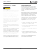
14. VIEW ERROR LOG
A list of the errors in the order they occurred will
scroll once on the display. All errors are logged
in memory. Only door error is displayed on the
display and has an audible signal.
E0:
Door 1 (upper) open.
E1: Thermistor 1 open.
E2: Thermistor 2 open.
E3: Thermistor 3 open.
E4: Thermistor 4 open (Does not apply to this
model).
E5: Thermistor 1 shorted.
E6: Thermistor 2 shorted.
E7: Thermistor 3 shorted.
E8: Thermistor 4 shorted (Does not apply to this
model).
E9: Door 2 (lower) open.
P1: Pump Circuit open (Does not apply to this
model).
15. CLEAR ERROR LOG
To clear errors, press and hold
(5 seconds)
when CLR is flashing.
16. THERMISTOR — 1 DIFFERENTIAL
This number should not be adjusted.
17. EVAPORATOR FAN DELAY IN MINUTES —
ON
“Fan Delay On” is the amount of time in minutes
the fan will be delayed from starting from the
beginning of a cooling cycle. Adjustable 0-99
minutes.
18. EVAPORATOR FAN DELAY IN MINUTES —
OFF
“Fan Delay Off” is the amount of time in minutes
the fan will continue to run at the end of a
cooling cycle. Adjustable 0-99 minutes.
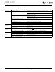
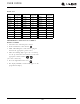
19. INDIVIDUAL COMPONENT TOGGLE
20. MODEL NUMBER INDICATOR
Displays the two-digit model number of the
specific unit. See model list table.
21. LIGHT ALL LED SEGMENTS
This will illuminate all the LEDs on the display to
ensure they work properly.
22. VIEW DEFROST CYCLES
Displays the number of defrosts that have
occurred in the past 24 hours.
23. VIEW COMPRESSOR RUNTIME
This will show the number of minutes the
compressor has run in the prior cycle (or
current cycle if the compressor was running
when service mode was entered).
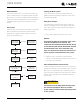
24. ACTIVATE DEFROST/HARVEST
Turns on the hot gas bypass valve allowing hot
gas to circulate through the evaporator causing
frost to melt.
25. RESTORE FACTORY DEFAULTS
Will restore all adjustable functions to their
factory settings.
26. SOFTWARE VERSION — MAIN BOARD
Displays software version of the main control
board.
27. SOFTWARE VERSION —
USER INTERFACE
Displays software version of the user interface.
28. LOG IN PERIOD
Factory use only - do not adjust.
29. FACTORY TEST MODE
Should be 0.
0. EXIT SERVICE MODE
Display # Relay/Output
0 Exit
2 Relay 2
3 Relay 3
4 Relay 4
5 Relay 5
6 Relay 6
7 Relay 7
8 DC Output 1
9 DC Output 2
10 DC Output 3
11 DC Output 4
12 DC Output 5
SEE RELAY/OUTPUT CHART
49